SS-T: 4080 Transient Analysis
Run Dynamic Transient Analysis in SimSolid.
- Purpose
- SimSolid performs meshless structural
analysis that works on full featured parts and assemblies, is tolerant of
geometric imperfections, and runs in seconds to minutes. In this tutorial,
you will do the following:
- Create Dynamic Transient Analysis.
- Model Description
- The following model file is needed for this tutorial:
- Transient.ssp
-

Figure 1.
Open Project
-
Click the
 (Open Project) icon.
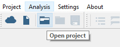
Figure 2.
Create Modal Analysis
-
On the main window toolbar, click the
 (Modal analysis) icon.
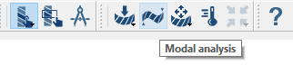
Figure 3.
Create Immovable Contraint
-
In the Analysis Workbench, click
 (Immovable support).
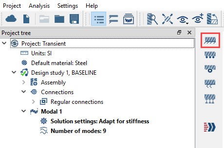
Figure 4. -
In the modeling window, select the faces shown in Figure 5.
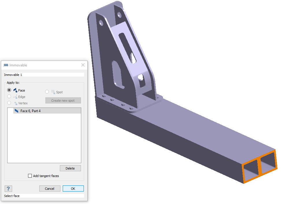
Figure 5.
Run Analysis
- In the Project Tree, open the Analysis Workbench.
-
Click
 (Solve).
Review Results
-
On the Analysis Workbench, select
 > Displacement Magnitude.
The Legend window opens and displays the contour plot. The Frequency (Hz) window opens and lists the modes.
> Displacement Magnitude.
The Legend window opens and displays the contour plot. The Frequency (Hz) window opens and lists the modes.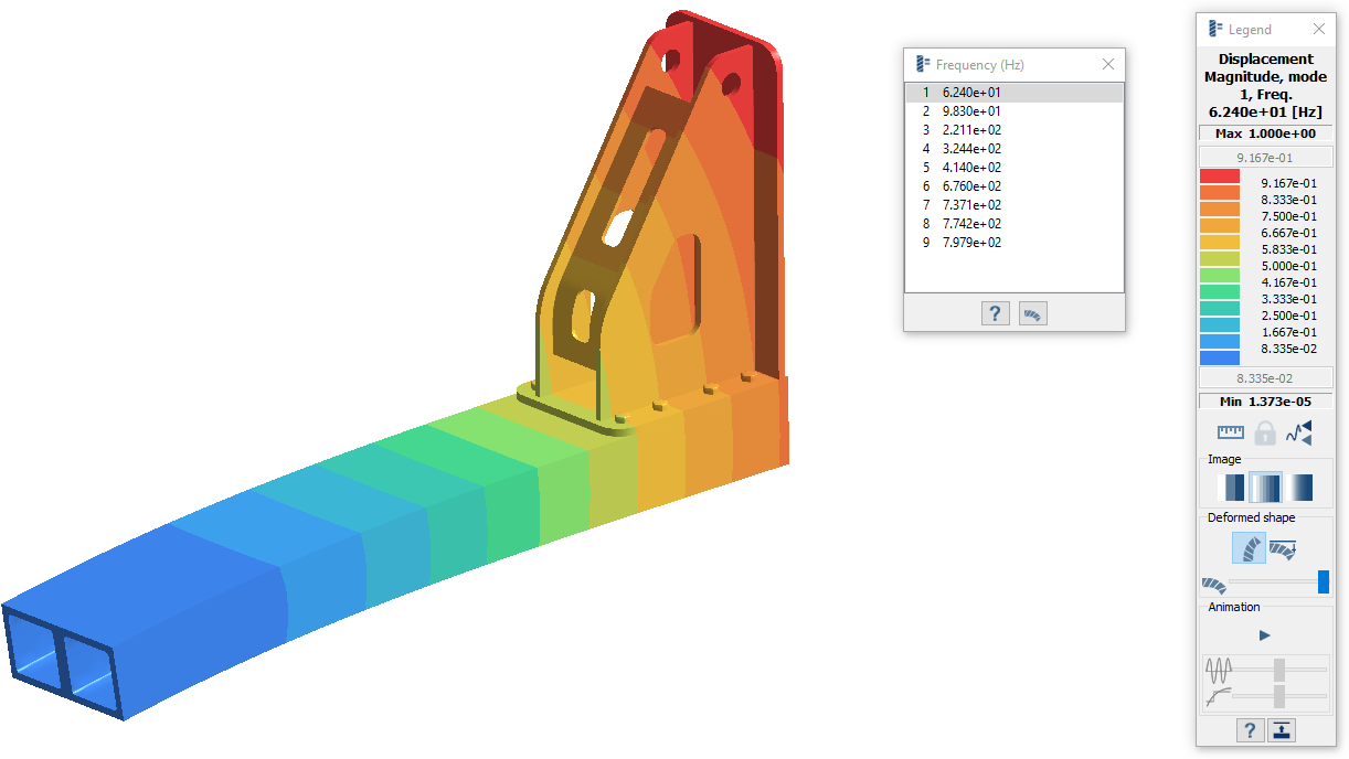
Figure 6. -
View the mode shapes.
- In the Frequency (Hz) window, highlight a mode in the list.
-
In the Legend, click
 (Start animation).
- Cycle between the other modes in the list.
Create Transient Analysis
-
On the main window toolbar, select
 > Trasient.
The Transient dynamics setup dialog oprnd and automatically links to the Modal analysis results.
> Trasient.
The Transient dynamics setup dialog oprnd and automatically links to the Modal analysis results.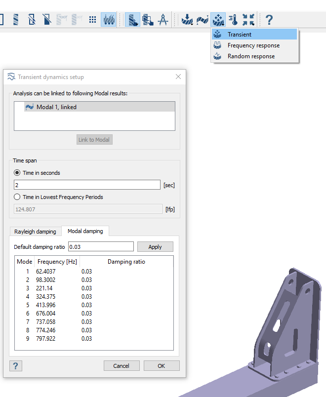
Figure 7.Note: If multiple Modal analyses with results are present in the design study, you must create the link manually. An example is shown in Figure 8.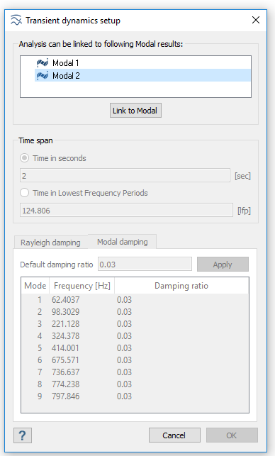
Figure 8.
Create Time Function
-
On the workbench toolbar, click the
 (Time function) icon.
-
In the Time functin dialog, click
Standard.
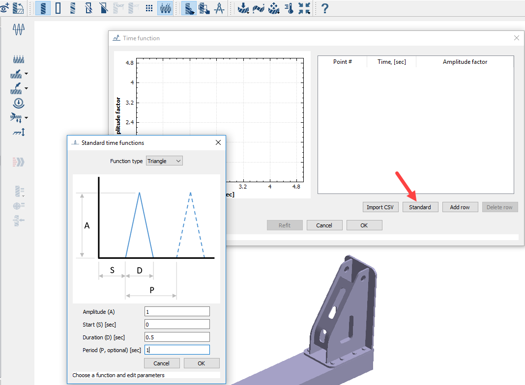
Figure 9.
Define Load
-
In the workbench toolbar, select
 > Force/Displacement.
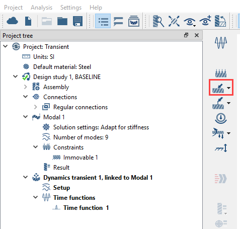
Figure 10. -
Select the spot as shown in Figure 11.
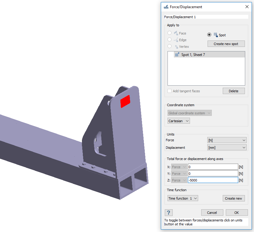
Figure 11.
Run Analysis
- In the Project Tree, open the Analysis Workbench.
-
Click (Solve).
Review Results
-
On the Analysis Workbench, select > Displacement Magnitude.
The Legend window opens and displays the contour plot. The Dynamics time response window opens. You can use the slider to change the time at which the result is being displayed.
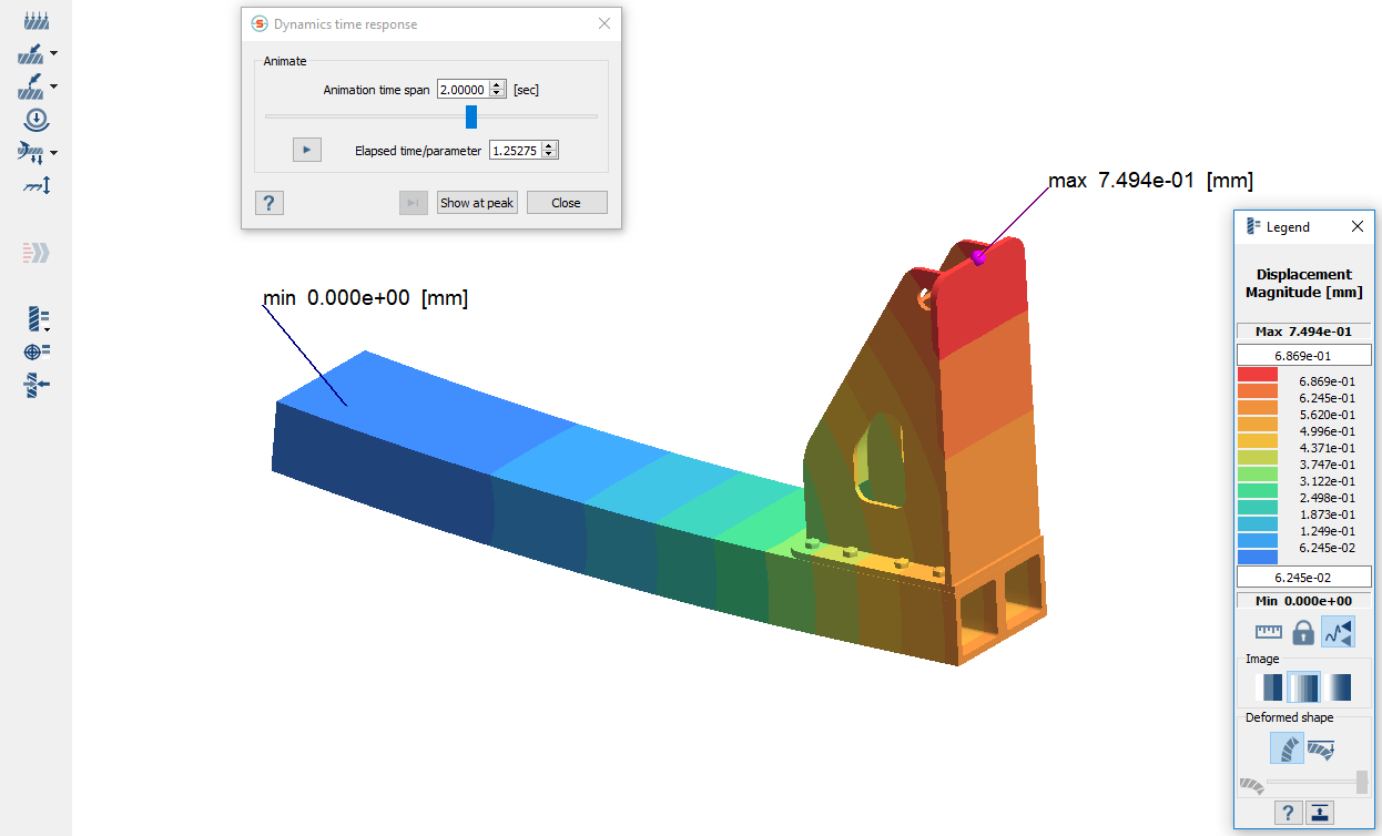
Figure 12. -
Click to animate the model.