Silhouette
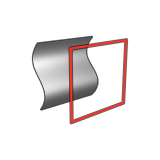
Extract the 2D or 3D silhouette curve of one or more selected objects while maintaining construction history.
- On the ribbon, click the Curves tab.
-
Click the Silhouette icon.
-
Select one or more objects. Right-click to confirm.
By default, a 2D silhouette curve is created within the x-z plane.
- Optional:
Define the output type:
- Planar Output: Extract a 2D silhouette curve.
- 3D Output: Extract a 3D silhouette curve.
Note: Double-click the curve to edit. - Optional:
You can adjust the direction of the silhouette curve by selecting one of the
following options:
- Global X Axis: Lock the x direction, so that the silhouette curve is in the y-z plane.
- Global Y Axis: Lock the y direction, so that the silhouette curve is in the x-z plane.
- Global Z Axis: Lock the z direction, so that the silhouette curve is in the x-y plane.
- Custom: Set the silhouette curve in a custom direction by dragging the Phi angle arrow or the Direction point. This may affect the shape of the silhouette curve.
- Set as Current View: Position the silhouette curve along the axis that is perpendicular (normal) to the active modeling view.
- Optional:
You can move the silhouette curve:
- To snap the origin to another object, drag the Origin point.
- To move the plane of a 2D silhouette curve, drag the Move projection plane point.
- Right-click and mouse through the check mark to exit, or double-right-click.