View Set
Create view sets of the selected parts of a model. Each view set displays a parent view of the selected part in the orthographic view and child views in the orthographic or isometric view.
First, you need to create a drawing sheet.
View sets have construction history. When the object is updated, the view set is updated accordingly.
-
Click the View Set icon.
The modeling environment is displayed. -
Do one of the following:
- If you want to the view direction to be correspond to the View Cube,
right-click to confirm the selection.
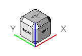
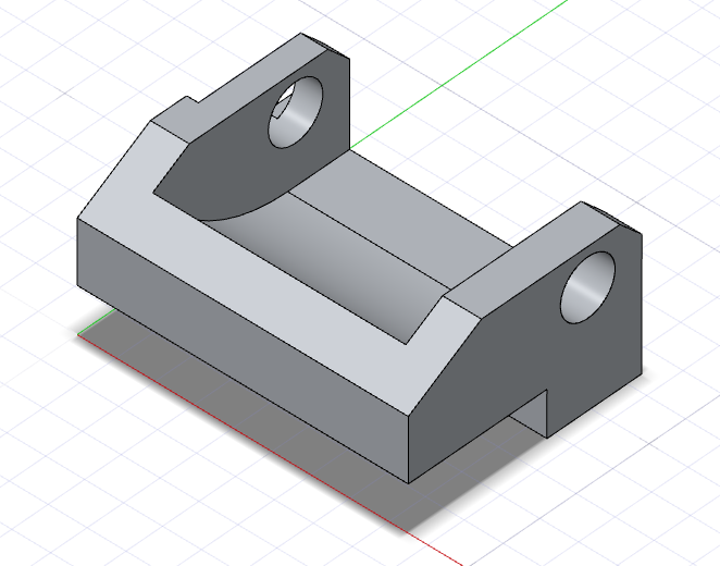
Figure 1. Example 1A: Standard View Direction - Corresponds to View Cube. Right-click to confirm. See Step 7 for more details. - If you want the view direction to be relative to a face of the model, in
the guide bar, click Custom Direction, and then
select the desired face.
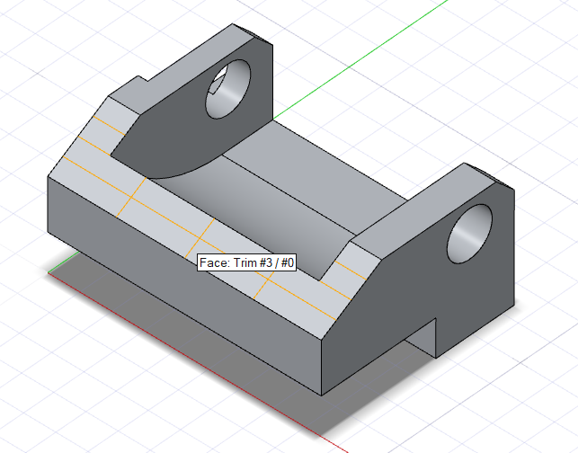
Figure 2. Example 1B: Custom View Direction - Corresponds to Selected Face. Do not right-click. Instead, in the guide bar, click Custom Direction, and then select the face highlighted in yellow. See Step 7 for more details.
- If you want to the view direction to be correspond to the View Cube,
right-click to confirm the selection.
-
To modify the view set, click Properties
 .
.
- View Direction (Parent View): Choose from
Front, Top,
Bottom, Rear,
Left, Right,
Top-Left, Top-Right,
Bottom-Left,
Bottom-Right.Note: By default, the View Direction corresponds to the faces of the View Cube. To set a Custom View Direction, see Step 4.
Figure 3. Example 1A: Standard View Direction - Corresponds to View Cube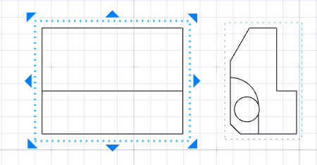
Figure 4. Example 1A: Front Corresponds to the Front Face of the View Cube. Parent view (orthographic) with child view (isometric).
Figure 5. Example 1B: Custom View Direction - Corresponds to Selected Face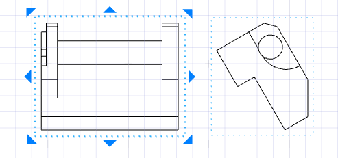
Figure 6. Example 1B: Front Corresponds to the Selected Face. Parent view (orthographic) with child view (isometric). - Rotation (Parent View): Define the rotation.
- External frame: Draw a thin black frame around the selected drawing.
- Hidden lines: Draw light, thin lines delineating the geometry underneath the viewing surfaces.
- Hatch lines (Section View): Draw closely spaced parallel lines to create tonal or shading effects.
- Custom Scale: Define a custom scale for the selected view.
- View Direction (Parent View): Choose from
Front, Top,
Bottom, Rear,
Left, Right,
Top-Left, Top-Right,
Bottom-Left,
Bottom-Right.