Cage
Create cages to morph objects. The cage starts out as a box, but you can modify the control points to create any shape you want. You can create up to 10 cages around multiple objects. The cages can be independent, or they can have a parent-child relationship, allowing you to easily deform subfeatures.
- On the ribbon, click the Deform tab.
-
Click the Cage icon.
-
Select one or more objects, and then right-click to confirm.
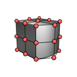
By default, the cage starts out as a box with four points along each side with a degree of 3.
- See Step 2 of Rename, Add, Remove, or Duplicate Cages, Set Up the Cage, or Morph the Object.
- Right-click and mouse through the check mark to exit, or double-right-click.
Rename, Add, Remove, or Duplicate Cages
You can create up to 10 cages around multiple objects. The cages can overlap. The cages can be independent, or they can have a parent-child relationship (except rigid body cages), allowing you to easily deform subfeatures.
- Double-click the cage to enter editing mode.
-
In the guide bar, select Edit Cages. In the
Cage Editor dialog, you can do the following:
To Do this Note Rename a cage Select the cage in the list, and then type a new name. Create a new independent cage - Click Add.
- The new cage overlaps the original cage. Press W to open the Move tool and move and scale the new cage.
Remove a cage - Select a cage.
- Click Remove.
If there is only one cage in the list, it cannot be removed. If you remove a parent cage, the child is not removed. The child becomes the new parent.
Duplicate a cage - Select a cage.
- Click Duplicate.
- The duplicate overlaps the original cage. Press W to open the Move tool and move the duplicate.
Child cages cannot be duplicated. Only the top level cage is duplicated. Create a new independent cage that allows the object to retain its shape during morphing - Click Add Rigid Body Cage.
- The rigid body cage overlaps the original cage. Press W to open the Move tool and move and scale the rigid body cage. Verify that all the areas that you don't want to be morphed are inside the rigid body cage.
- Optional: Adjust the Smoothing Distance to fine-tune the degree of blending between the rigid body and the rest of the object.
Now when you modify another cage, the area inside the rigid body cage won't be morphed.
For example, you can use this feature to maintain the shape of holes inside an imported model, or to preserve the grille of a car while smoothing the sides of the car. Rigid body cages cannot have a parent-child relationship.
- Right-click and mouse through the check mark to exit, or double-right-click.
Set Up the Cage
Modify the cage without morphing the object.
- Double-click the cage to enter editing mode.
-
On the Control Panel, select the Setup tab.
To Do this Note Move and scale the entire cage - Make sure that no control points are selected.
- Press W to use the Move tool.
Select multiple control points - Use box selection.
- Hold down Ctrl while clicking the control points.
- Click a control point. While holding down Alt, click another control point. The control points in between are now selected too.
Move control points - Optional: Select multiple control points.
- Do one of the following:
- Drag the control points.
- Select the control points, and then press W to use the Move tool. If you don't select the control points, then you'll be moving the entire cage.
To move the control points back to their default positions, in the Control Panel, click Fit to Bounding Box. Edit the control points symmetrically - In the Control Panel, under
Symmetry, select one of the
following options:
- Red: Orient the symmetry plane along the red plane.
- Green: Orient the symmetry plane along the green plane.
- Blue: Orient the symmetry plane along the blue plane.
- Now you can edit the control points symmetrically in real-time.
If you don't want to edit the control points symmetrically, select None (default). Mirror one side of a symmetric cage - Click Make Symmetric.
- To mirror control points that you've already modified across the symmetry plane, select the Side to Mirror. If you haven't yet modified any control points, it doesn't matter which side you select.
Slide control points along an edge - Optional: Select multiple control points.
- Optional: To slide the control points along
their local x-, y-, or z-axis instead of the same
direction as the dragged arrow:
- Optional: In the Control Panel, select Local Edge Sliding.
- Select one of the following:
- Exact Distance (default): Move the control points the same exact distance along their edges.
- Relative Distance: Move the control points the same relative distance along their edges. For example, sliding a selected point halfway along an edge will slide the other selected points halfway along their edges.
- Hover around a control point, and then drag one of the arrows.
Adjust the area that will be smoothened - To show the areas that will be smooth, in the Control Panel, select Show Area of Influence.
- Enter a Smoothing Distance.
Add rows of control points - In the Control Panel, click Add Sections.
- Hover over the cage to preview where the section will be added. Press Shift to change the direction.
- Click to add sections.
Distribute control points evenly - Select the desired control points.
- Right-click, and then select Spread Points Evenly Along All Axes, Spread Evenly Along Red, Spread Evenly Along Green, or Spread Evenly Along Blue.
Align control points - Select the desired control points.
- Right-click, and then select Align Points Along Red, Align Points Along Green, or Align Points Along Blue.
Project control points onto a curve - Draw the curve whose shape you'd like the control points to follow, and position it as desired.
- On the cage, select the control points that you'd like to project onto the curve.
- Right-click, and then select Project Points onto a Curve.
- Select the curve.
This is useful for creating a curved cage around a curved object with more precision. For example, a circular cage around a hole or a curved cage around the front of a car as shown in the video. Remove rows of control points - In the Control Panel, click Remove Sections.
- Select the sections and press Delete.
Change the degree In the Control Panel, enter the Degree Along Red, Degree Along Green, and Degree Along Blue. If you increase the degree, you need to increase the number of points. Preview the areas that will be deformed by the entire cage In the Control Panel, select Show Area of Influence. - Green indicates areas that will be deformed.
- Red indicates areas that won't be deformed.
- Yellow indicates boundaries, which will be partially deformed.
Now you can see which control points you need to move in order to deform the areas you want. - Right-click and mouse through the check mark to exit, or double-right-click.
Morph the Object
Deform the object while modifying the cage.
- Double-click the cage to enter editing mode.
-
On the Control Panel, select the Morph tab.
To Do this Note Move and scale the entire cage - Make sure that no control points are selected.
- Press W to use the Move tool.
Select multiple control points - Use box selection.
- Hold down Ctrl while clicking the control points.
- Click a control point. While holding down Alt, click another control point. The control points in between are now selected too.
Not available for rigid body cages. Move control points - Optional: Select multiple control points.
- Do one of the following:
- Drag the control points.
- Select the control points, and then press W to use the Move tool. If you don't select the control points, then you'll be moving the entire cage.
- Optional: To move the control points back to their default positions, in the Control Panel, click Reset Cage.
Not available for rigid body cages. Slide control points along an edge - Optional: Select multiple control points.
- Optional: To slide the control points along
their local x-, y-, or z-axis instead of the same
direction as the dragged arrow:
- In the Control Panel, select Local Edge Sliding.
- Select one of the following:
- Exact Distance (default): Move the control points the same exact distance along their edges.
- Relative Distance: Move the control points the same relative distance along their edges. For example, sliding a selected point halfway along an edge will slide the other selected points halfway along their edges.
- Hover around a control point, and then drag one of the arrows.
Not available for rigid body cages. Partially displace a cage - Select the cage.
- In the Control Panel, enter a Displacement (%).
Not available for rigid body cages. There is a Displacement value for every cage. For example, if you have 3 cages, there will be 3 Displacement values:
- [Cage Name] (%)
- [Cage Name] (%)
- [Cage Name] (%)
Modify the tolerance In the Control Panel, enter an Accuracy [%]. The maximum value is 100%. Changing the Accuracy [%] may slow down the operation or cause it to fail.
Reapply a blend operation from a source object such as a round In the Control Panel, select Reblend. Adjust the area that will be smoothened - To show the areas that will be smooth, in the Control Panel, select Show Area of Influence.
- Enter a Smoothing Distance.
Not available with rigid body cages. Hide the control points In the Control Panel, turn off Show Morph Points. When your model has many control points, use this option to temporarily hide the control points so that you can more easily see the deformed model. Show the areas that will be deformed by the selected control points - In the Control Panel, select Show Area of Influence.
- Select one or more control points. Green indicates the area that will be deformed by moving the selected control points.
- Right-click and mouse through the check mark to exit, or double-right-click.