Tutorial: Basic PolyNURBS

Explore the basics of creating and editing PolyNURBS, and how to export the model to a 3D printer.

In this lesson you will learn how to:

  • Create primitive PolyNURBS
  • Edit PolyNURBS
  • Add edge loops
  • Chamfer edges
  • Extrude faces
  • Bridge faces
  • Use NURBS tools with PolyNURBS
  • Export to 3D printing using the NURBS to Poly tool


Create the Basic Shape

  1. Start Inspire Studio. Or if it is already open, click the New model tool on the File icon.


  2. In the Perspective view, click the Front face of the View Cube to switch to the orthogonal front view.
  3. Make sure that Grid Snap #1 (Alt+1) is turned on.
  4. On the PolyNURBS tab, in the Primitives tool group, select the PolyDisk tool.
  5. Let's draw the PolyDisk.
    1. Drag to define the outer diameter.
    2. Click inside the disk to define the inner diameter.
    3. Edit the inner diameter to 1.75 cm and outer diameter to 2 cm.
    4. In the guide bar, increase the Radial Subdivisions from 1 to 4.
    5. Click the green check mark.
      The Edit PolyNURBS Control Panel is automatically displayed.
    6. Right-click and mouse through the check mark to exit, or double-right-click.
  6. To help with later steps of this tutorial, we want to place the center of the PolyDisk at 0, 0, 0.
    1. Select the PolyDisk object.
    2. Press W to open the Move tool.
    3. In the Control Panel, enter 0 for all values of the Manipulator.

Extrude Faces

  1. Click the PolyDisk to select it.
  2. Press D to enter Edit Faces mode.
  3. Right-click, and then click Select All Faces.
  4. In the view controls at the bottom left of the modeling window, click the Home View icon to return to the default ISO view.
    At this point, you may notice that the camera is further away from the object than desired. You can zoom in to the desired level and set a new home position by holding down Ctrl while clicking on the Home View icon.
  5. Ensuring that all faces are still selected, hover the mouse over any one of the selected faces to bring up the extrude handle.
  6. Drag the red part of the graphic to extrude along the normal. In the pop-up text box, type 0.5 cm and click Done.
  7. Right-click and mouse through the check mark to exit, or double-right-click.
    Note: The blue sphere of the extrude graphic lets you extrude a face freely or along X, Y, and Z. The blue part of the graphic helps in extruding the face along the normal.

Add Edge Loops

  1. Select the PolyNURBS object.
  2. On the PolyNURBS tab, select the Edge Loop tool.

  3. Increase the Subdivision Snap value to 3 and turn on Multiple Split
  4. Move the mouse over one of the top faces of the PolyNURBS to see the preview of the 3 edge loops. Click anywhere to add the 3 loops.
  5. Right-click and mouse through the check mark to exit, or double-right-click.
    Note: If you invoked the Edge Loop tool without selecting any object, you will need to click the PolyNURBS button in the guide bar to go into selection mode and then select the object. This applies to most PolyNURBS tools.

Select Multiple Loops and Add a Chamfer
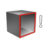
  1. Go to edge editing mode using the keyboard shortcut S or clicking the option in the Control Panel.
  2. Holding down Alt, move the mouse over the edge of the disk.
  3. The entire loop is highlighted. Click to select the first loop.
  4. Holding down Ctrl+Alt, select the edge loops at the extremities as shown.
  5. Zoom in closer. Holding down just the Alt key, hover the mouse over the center of any one of the edges to bring up the chamfer graphic handle.
  6. When the graphic turns a solid orange, drag it to add a chamfer to the entire selection.

Delete Faces

For symmetric objects, it is easier to create 1/4 of the object and later create a radial symmetry. We will select all unwanted faces and delete them in this step.
  1. Switch to Front view.
  2. Select the object.
  3. Press D to enter faces editing.
  4. Using box selection, select 1/4 of the faces.
  5. Right-click and select Invert Selection.
  6. Right-click and select Delete Selected Faces.

Bridge Faces

  1. Select the object.
  2. Go to faces editing (D).
  3. Select 4 alternating faces on the edges as shown (hold down Ctrl to add to the selection).
  4. Extrude the faces like we did in Step 2, but this time extrude it two times by 0.125 cm. This automatically adds a loop between the two extrusions.
  5. Create a bridge between two faces by selecting them, right-clicking, and then selecting Bridge.
  6. For the set of faces, we will extrude it once more by 0.125 cm and create another bridge as shown.
    Note: If you see strange artifacts at this point, with the PolyNURBS object in vertex, edge, or face editing mode (A, S, or D), right-click and select Clean Up.

Edge Strength and Sharpness

  1. Select the object.
  2. Press N to Nurbify.
  3. Go to edges editing (S),
  4. Select the top edges of the upper bridge using Ctrl. In the Control Panel, for Strength, enter a value other than 0. A higher value corresponds to a stronger crease.
  5. Select the top edges of the lower bridge and turn on the Sharp option.
    Note: Some options are only available in Nurbify and are hidden when the object is in a mesh state (polygonal state).

Radial Symmetry

  1. Select the object.
  2. Press N to turn off Nurbify.
  3. On the Modify tab, select the Radial Symmetry tool.

  4. Select the PolyNURBS.
  5. Create 4 copies around the center or origin (0,0,0).
  6. Right-click and mouse through the check mark to exit, or double-right-click.
  7. Press any one of the PolyNURBS editing shortcut keys (A, S, D) and a PolyNURBS Edit prompt is shown. Click Yes to create a copy for editing.
  8. Press N to Nurbify.
  9. Run a Clean Up to solve any mesh inconsistencies.

Export for 3D Printing

Before we export for 3D printing, we want to ensure that the object is a closed solid.
  1. Select the object.
  2. On the Analysis tab, select the Tolerance Check tool.

  3. In the Control Panel, make sure it says Closed Solid.
  4. On the PolyNURBS tab, select the NURBS to Poly tool.

  5. Select the object.
  6. In the Control Panel, change the Tessellation from View to Advanced.
  7. A new set of options are available. The most important one here is the face dimension that lets you control the detail of the 3D printed model.

    A smaller face dimension corresponds to finer details and subsequently a larger file size.

  8. Click the green check mark to finalize the tessellation.
  9. On the File menu, select Save Selected.
  10. Choose the STL file type.
  11. Leave the default options and click OK.