Using Virtual Wind Tunnel for ultraFluidX
Use Virtual Wind Tunnel for ultraFluidX to perform an external aerodynamic analysis of a vehicle.
- Install the most recent version of ultraFluidX. If you are running Virtual Wind Tunnel on a Windows system, you'll need to have a Linux installation of ultraFluidX available for running the solver. If you are running Virtual Wind Tunnel on a Linux system with a supported GPU, no further configuration steps are necessary. The ultraFluidX solver is included in the installation package. If you wish to run a different version of the solver than the one that is shipped with the Virtual Wind Tunnel package, the installation directory of the alternate solver installation can be set under .
- The geometry of the vehicle is described by a surface mesh which can be in a variety of formats (see Supported File Formats for more information). Unlike many other CFD solvers, the ultraFluidX package does not require a water tight surface mesh. This greatly reduces the pre-processing burden when simulating complex geometries.
- The surface mesh of the vehicle is expected to be in meters [m]. If it is not, use the scale option to scale it to meters.
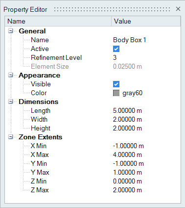
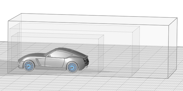
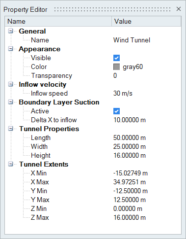
- It is assumed that the wind tunnel has its inflow surface at the minimum x-coordinate of the wind tunnel and the flow is going in the positive x-direction. The y-direction is perpendicular to the flow direction and parallel to the wind tunnel ground. The z-direction is perpendicular to the ground of the wind tunnel.
Invoke Virtual Wind Tunnel for ultraFluidX
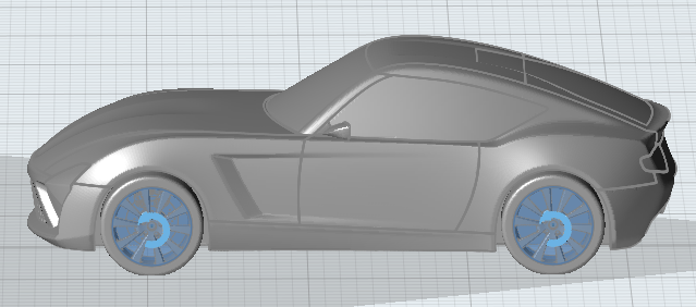
Import the Surface Mesh Model
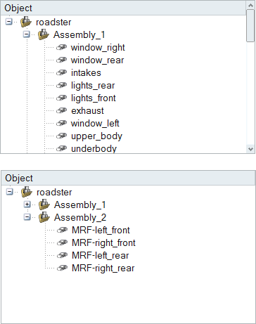
There are two files that need to be imported for this tutorial. The first is a surface mesh model in standard Nastran format. The second is an STL file used to model moving reference frames.
On Windows platforms, the model files are located at: <installation_directory>/hwx/help/VWT/Models/.
On Linux platforms, the model is located at: <installation_directory>/.altair/hwx/help/VWT/Models/.
Define Wind Tunnel Dimensions
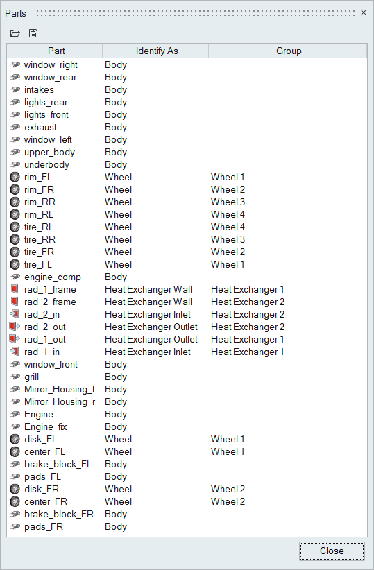
Identify Parts
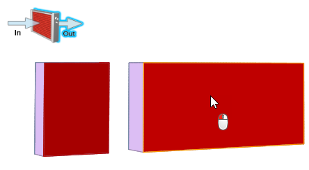
Use the Identify Parts tool to define types of parts like wheels, heat exchangers or body panels, which require specific modeling techniques for the CFD run.
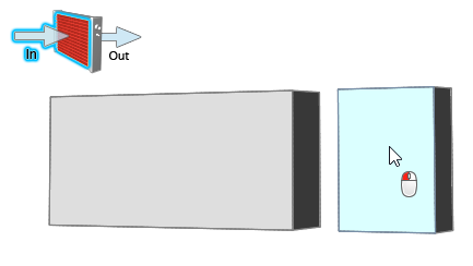
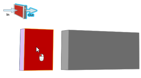
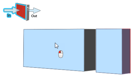
Specify the Heat Exchangers
Specify the Wheels
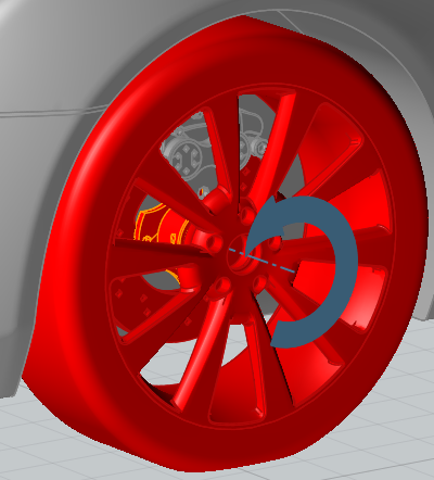
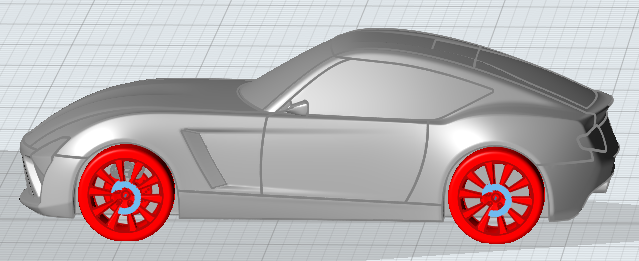
You need to select the parts forming the wheel, for example tire and rim. All other parameters like center of rotation, axis of rotation, and the angular velocity (in RPM) are computed automatically. If multiple parts are selected, Virtual Wind Tunnel will group the parts into one or more wheels. For example, if you select the brake disc, the rim and the tire of the left front wheel, all three parts will be identified as wheel_1. If you also select the rim and the tire of the left rear wheel, those parts will be grouped into wheel_2.
Specify the MRF Regions
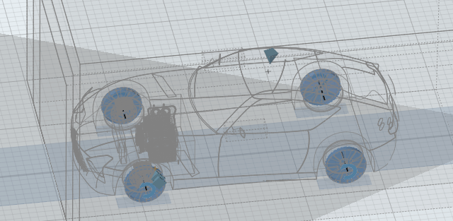
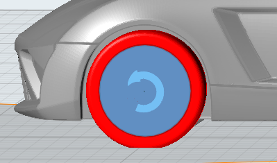
MRF regions define a volume in which the governing equations are solved in a rotating reference frame. This transformation of the equations can lead to higher accuracy for rotating bodies due the addition of centrifugal and Coriolis forces.
 on the guide bar to clear a selection.
Review Identified Parts
Define the Mesh Controls
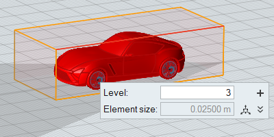
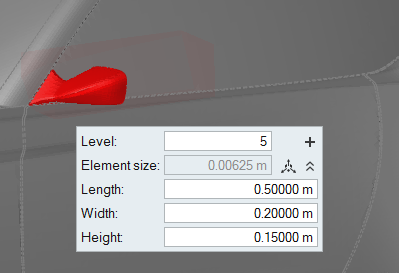
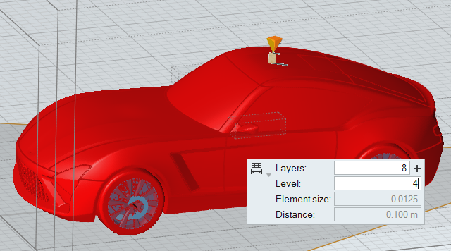
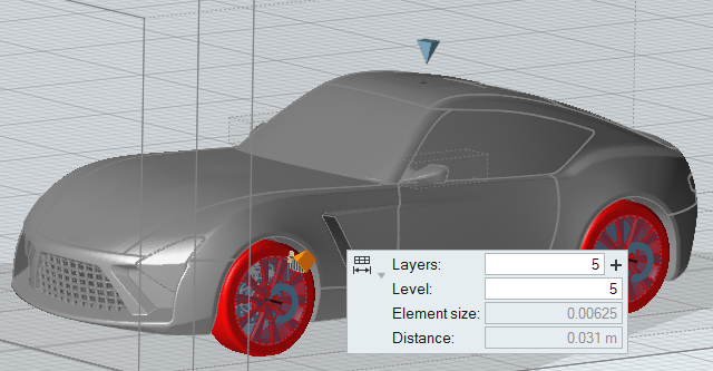
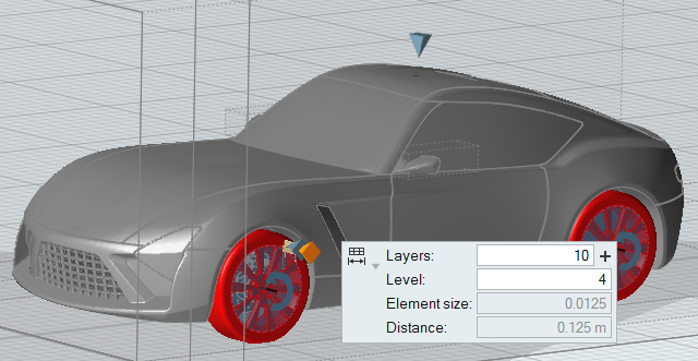
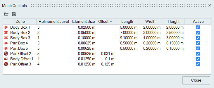
Use the Mesh Controls tool to define regions with a user-defined volume element size.






 on the