Creating the Model
Create the model in CADFEKO. Define any ports and sources required for the model. Specify the operating frequency or frequency range for the model.
-
Add microstrip ports to the edges of the feedline (see Figure 1 and Figure 2).
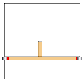
Figure 1. Microstrip ports were added to the edges of the feedline. Note that the infinite plane is hidden and a cutplane was added to show the port locations.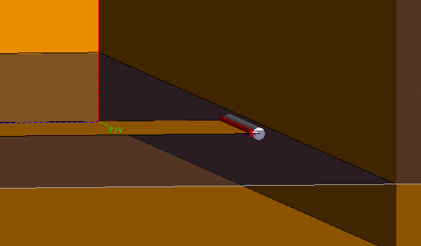
Figure 2. Zoomed in 3D view of one of the microstrip ports.Tip: The microstrip port connects to a single edge and is only used with infinite substrates. The positive terminal is indicated by the red cylinder in the 3D view.