Periodic Boundaries (Cylindrical)
Cylindrical Periodic Boundaries can be set inside a simulation. Unlike the Linear Periodic Boundaries, which act on the Domain Bounding Box, the Cylindrical Boundaries are set by the user and exist inside the domain.

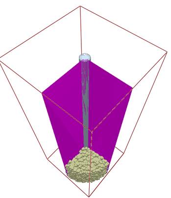
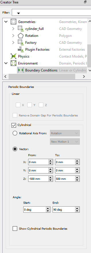
Any particles exiting the boundary plane will enter the opposing plane and all forces, torques, positions and velocities will be rotated by the difference in angle between the two planes. Selecting the  icon or ticking the box in the setting menu allows the boundary to be visualized.
-
A cylindrical periodic boundary can be defined using the axis from a rotational kinematic or a vector based on a start or end point.
-
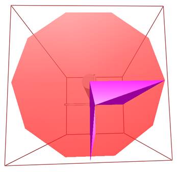
Set the angle of the boundary as appropriate for the simulation. In the image below the mixer has 4 blades at 90 degrees separation. In this case the angle should be 90 degrees.
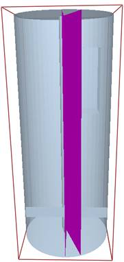
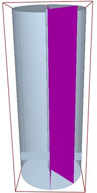
Image above: Boundary showing 20, 45 and 90 degrees.
Cylindrical Periodic Boundary Known Issues and Limitations:
-
A Linear Rotational kinematic is required to setup the boundaries, even if the kinematic has a velocity magnitude of 0.
-
Plugin (API) factories are not supported with Cylindrical Boundary Conditions.
-
Simulator Auto Grid Size is not supported with Cylindrical Boundary Conditions.
-
Coupling Interface is not supported with Cylindrical Boundary Conditions.
-
GPU Solver is not supported with Cylindrical Boundary Conditions.
-
Cylindrical Boundaries are limited to a maximum 150 degree angle.
-
Cylindrical Boundaries cannot be used at the same time as Linear Boundaries.
-
Cylindrical Periodic Boundaries are not compatible with the bonded model.
-
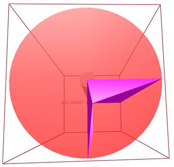
Geometry must be rotationally periodic to use the boundary effectively. The two images below show a circle made from 10 edges and one made from 50 edges. If the geometry is not of a high-quality mesh then particles passing through boundaries will catch on non-periodic edges.
-
A central element (cylinder) is required at the mid-point of the boundary. At the center point of the boundary it is possible for a particle to pass through the boundary and contact itself, which can lead to particle explosions. This can be prevented through definition of a geometry section at the center of the boundary.