 Package HydraulicsByFluidon.Components.Valves.DirectionalValves
Icon for standard packages
Package HydraulicsByFluidon.Components.Valves.DirectionalValves
Standard package icon.
Extends from Modelica.Icons.Package (Icon for standard packages).
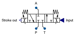
 Model HydraulicsByFluidon.Components.Valves.DirectionalValves.SwitchingValve22
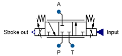
The component SwitchingValve22 is a model of a 2-way valve which will open for input signals equal or above Input threshold to open the valve.

Opening and closing times of the valve are set by Time to close 100 % - 0 %/Time to open 0 % - 100 %, the movement is linear with constant speed until the respective end stop is reached.
The valve stroke can be shifted by Relative overlap. In accordance with common valve parameters a negative overlap will open the valve edge.
The default relationship between input signal and flow rate of the metering edge is linear, but can be changed through the use of a 1D look-up table. The look-up table is provided either manually or by importing a text file. If the parameter Table is provided by file is set to false, the manually entered datapoints from Manually provided look-up table will be used. If it is set to true, the table Table name on file from the file File where look-up table is stored will be utilized.
The text file must follow a specific syntax such that it can be read by Modelica. The input values as well as the output values must lie within the range from 0 to 1. An output value of 1 (100 %) corresponds to a fully-opened metering edge. An example for a properly formatted text file with two tables is given in the figure below:
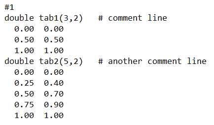
A table is declared by its datatype (e. g. double), followed by the table name (e. g. tab1) and its dimensions in brackets (e. g. (5,2)). As can be seen, multiple tables can be defined in the same text file. The table declaration is followed by the actual data. The first column of the table represents the input of the 1D table, whereas the second column lists the corresponding output values. The input values of the table must be in increasing order. The component interpolates linearly between the listed input values. More information regarding the format of tables can be found at CombiTable1D.
Extends from HydraulicsByFluidon.Components.Valves.Base.PartialValve22 and HydraulicsByFluidon.Components.Valves.Base.PartialValveControlSignal_x2.
| Type | Name | Default | Description |
|---|---|---|---|
Real | SwitchingThreshold | 0.5 | input threshold to open the valve |
Time | Topen | 0.1 | Time to open 0 % - 100 % |
Time | Tclose | 0.1 | Time to close 100 % - 0 % |
Boolean | enableStrokeOut | false | Enable Stroke Output |
VolumeFlowRate | NominalVolumeFlow | 5e-4 | Nominal volume flow |
Pressure | NominalPressureDifference | 500000 | Nominal pressure difference |
Density | ReferenceDensity | 860 | Reference density for volume flow and pressure difference |
DimensionlessRatio | Overlap | 0 | Valve edge relative overlap |
Boolean | tableFromFile | false | Table is provided by file |
String | fileName | "NoFile" | File where look-up table is stored |
String | tableName | "NoTable" | Table name on file |
Real | manualTable[:,:] | [0,0; 1,1] | Manually provided look-up table |
VolumeFlowRate | ZeroVolumeFlow | 0 | Volume flow due to leakage |
Pressure | ZeroFlowPressureDifference | 500000 | Pressure difference for leakage flow |
Volume | deadVolume | 1e-6 | Dead volume at ports |
Init | initType | Modelica.Blocks.Types.Init.InitialState | Type of initialization (1: no init, 2: steady state, 3/4: initial output) |
| Type | Name | Description |
|---|---|---|
FluidPort | portA | Hydraulic port A |
FluidPort | portP | Hydraulic port P |
output RealOutput | valveStrokeOut | Valve Stroke |
input RealInput | Input | Set value of valve position |
 Model HydraulicsByFluidon.Components.Valves.DirectionalValves.SwitchingValve33
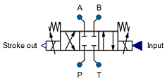
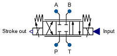
The component SwitchingValve33 is a model of a 3-way valve where the flow (at 100 % valve stroke) is set by NominalVolumeFlow and NominalPressureDifference.
For Input ≥ Input threshold to open the valve the valve switches in positive direction up to right position, for Input ≤ - Input threshold to open the valve the valve switches in negative direction up to left position. For - Input threshold to open the valve < Input < Input threshold to open the valve it switches into resting position (middle position).
The opening of the valve lasts always <>Time to open 0 % - 100 %<>, the closing always <>Time to close 100 % - 0 %<>, i. e. the switching from one end stop position to the other lasts <>Time to close 100 % - 0 %<> + <>Time to open 0 % - 100 %<>.
The valve stroke can be shifted by Valve edge general relative overlap. In accordance with common valve parameters a negative overlap will open the valve edge. Valve edge general relative overlap is applied to all valve edges simultaneously. If at least one of the edge-specific values, e. g. Valve edge PA relative overlap is set to a value different from 0, then Valve edge general relative overlap is ignored and the individual overlaps are used.
The default relationship between input signal and flow rate of the metering edge is linear, but can be changed through the use of a 1D look-up table. The look-up table is provided either manually or by importing a text file. If the parameter Table is provided by file is set to false, the manually entered datapoints from Manually provided look-up table will be used. If it is set to true, the table Table name on file from the file File where look-up table is stored will be utilized.
The text file must follow a specific syntax such that it can be read by Modelica. The input values as well as the output values must lie within the range from 0 to 1. An output value of 1 (100 %) corresponds to a fully-opened metering edge. An example for a properly formatted text file with two tables is given in the figure below:
A table is declared by its datatype (e. g. double), followed by the table name (e. g. tab1) and its dimensions in brackets (e. g. (5,2)). As can be seen, multiple tables can be defined in the same text file. The table declaration is followed by the actual data. The first column of the table represents the input of the 1D table, whereas the second column lists the corresponding output values. The input values of the table must be in increasing order. The component interpolates linearly between the listed input values. More information regarding the format of tables can be found at CombiTable1D.
Extends from HydraulicsByFluidon.Components.Valves.Base.PartialValve33 and HydraulicsByFluidon.Components.Valves.Base.PartialValveControlSignal_x3.
| Type | Name | Default | Description |
|---|---|---|---|
Real | SwitchingThreshold | 0.5 | input threshold to open the valve |
Time | Topen | 0.1 | Time to open 0 % - 100 % |
Time | Tclose | 0.1 | Time to close 100 % - 0 % |
Boolean | enableStrokeOut | false | Enable Stroke Output |
VolumeFlowRate | NominalVolumeFlow | 5e-4 | Nominal volume flow |
Pressure | NominalPressureDifference | 500000 | Nominal pressure difference |
Density | ReferenceDensity | 860 | Reference density for volume flow and pressure difference |
DimensionlessRatio | Overlap | 0 | Valve edge general relative overlap |
DimensionlessRatio | OverlapPA | 0 | Valve edge PA relative overlap |
DimensionlessRatio | QFactorPA | 1 | Factor for edge PA specific flow adjustment |
Boolean | tableFromFilePA | false | Table is provided by file |
String | fileNamePA | "NoFile" | File where look-up table is stored |
String | tableNamePA | "NoTable" | Table name on file |
Real | manualTablePA[:,:] | [-1,0; 0,0; 1,1] | Manually provided look-up table |
DimensionlessRatio | OverlapAT | 0 | Valve edge AT relative overlap |
DimensionlessRatio | QFactorAT | 1 | Factor for edge AT specific flow adjustment |
Boolean | tableFromFileAT | false | Table is provided by file |
String | fileNameAT | "NoFile" | File where look-up table is stored |
String | tableNameAT | "NoTable" | Table name on file |
Real | manualTableAT[:,:] | [-1,0; 0,0; 1,1] | Manually provided look-up table |
VolumeFlowRate | ZeroVolumeFlow | 0 | Volume flow due to leakage |
Pressure | ZeroFlowPressureDifference | 500000 | Pressure difference for leakage flow |
Volume | deadVolume | 1e-6 | Dead volume at ports |
Init | initType | Modelica.Blocks.Types.Init.InitialState | Type of initialization (1: no init, 2: steady state, 3/4: initial output) |
| Type | Name | Description |
|---|---|---|
FluidPort | portA | Hydraulic port A |
FluidPort | portP | Hydraulic port P |
FluidPort | portT | Hydraulic port T |
output RealOutput | valveStrokeOut | Valve Stroke |
input RealInput | Input | Set value of valve position |
 Model HydraulicsByFluidon.Components.Valves.DirectionalValves.SwitchingValve43
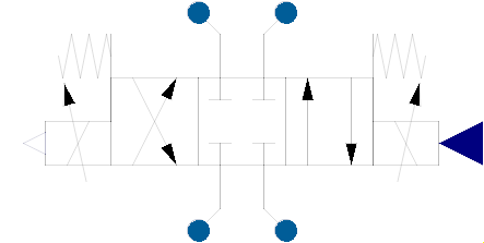
The component SwitchingValve43 is a model of a 3-way valve where the flow (at 100 % valve stroke) is set by Nominal volume flow and Nominal pressure difference.
For Input ≥ Input threshold to open the valve the valve switches in positive direction up to right position, for Input ≤ - Input threshold to open the valve the valve switches in negative direction up to left position. For - Input threshold to open the valve < Input < Input threshold to open the valve it switches into resting position (middle position).
The opening of the valve lasts always Time to open 0 % - 100 %, the closing always Time to close 100 % - 0 %, i. e. the switching from one end stop position to the other lasts Time to close 100 % - 0 % + Time to open 0 % - 100 %.
The valve stroke can be shifted by Valve edge general relative overlap. In accordance with common valve parameters a negative overlap will open the valve edge. Valve edge general relative overlap is applied to all valve edges simultaneously. If at least one of the edge-specific values, e. g. Valve edge PA relative overlap is set to a value different from 0, then Valve edge general relative overlap is ignored and the individual overlaps are used.
The default relationship between input signal and flow rate of the metering edge is linear, but can be changed through the use of a 1D look-up table. The look-up table is provided either manually or by importing a text file. If the parameter Table is provided by file is set to false, the manually entered datapoints from Manually provided look-up table will be used. If it is set to true, the table Table name on file from the file File where look-up table is stored will be utilized.
The text file must follow a specific syntax such that it can be read by Modelica. The input values as well as the output values must lie within the range from 0 to 1. An output value of 1 (100 %) corresponds to a fully-opened metering edge. An example for a properly formatted text file with two tables is given in the figure below:
A table is declared by its datatype (e. g. double), followed by the table name (e. g. tab1) and its dimensions in brackets (e. g. (5,2)). As can be seen, multiple tables can be defined in the same text file. The table declaration is followed by the actual data. The first column of the table represents the input of the 1D table, whereas the second column lists the corresponding output values. The input values of the table must be in increasing order. The component interpolates linearly between the listed input values. More information regarding the format of tables can be found at CombiTable1D.
Extends from HydraulicsByFluidon.Components.Valves.Base.PartialValve43 and HydraulicsByFluidon.Components.Valves.Base.PartialValveControlSignal_x3.
| Type | Name | Default | Description |
|---|---|---|---|
Real | SwitchingThreshold | 0.5 | Input threshold to open the valve |
Time | Topen | 0.1 | Time to open 0 % - 100 % |
Time | Tclose | 0.1 | Time to close 100 % - 0 % |
Boolean | enableStrokeOut | false | Enable Stroke Output |
VolumeFlowRate | NominalVolumeFlow | 5e-4 | Nominal volume flow |
Pressure | NominalPressureDifference | 500000 | Nominal pressure difference |
Density | ReferenceDensity | 860 | Reference density for volume flow and pressure difference |
DimensionlessRatio | Overlap | 0 | Valve edge general relative overlap |
DimensionlessRatio | OverlapPA | 0 | Valve edge PA relative overlap |
DimensionlessRatio | OverlapPB | 0 | Valve edge PB relative overlap |
DimensionlessRatio | OverlapAT | 0 | Valve edge AT relative overlap |
DimensionlessRatio | OverlapBT | 0 | Valve edge BT relative overlap |
VolumeFlowRate | ZeroVolumeFlow | 0 | Volume flow due to leakage |
Pressure | ZeroFlowPressureDifference | 500000 | Pressure difference for leakage flow |
Real | QFactorPA | 1 | Factor for edge PA specific flow adjustment |
Boolean | tableFromFilePA | false | Table is provided by file |
String | fileNamePA | "NoFile" | File where look-up table is stored |
String | tableNamePA | "NoTable" | Table name on file |
Real | manualTablePA[:,:] | [-1,0; 0,0; 1,1] | Manually provided look-up table |
Real | QFactorPB | 1 | Factor for edge PB specific flow adjustment |
Boolean | tableFromFilePB | false | Table is provided by file |
String | fileNamePB | "NoFile" | File where look-up table is stored |
String | tableNamePB | "NoTable" | Table name on file |
Real | manualTablePB[:,:] | [-1,0; 0,0; 1,1] | Manually provided look-up table |
Real | QFactorAT | 1 | Factor for edge AT specific flow adjustment |
Boolean | tableFromFileAT | false | Table is provided by file |
String | fileNameAT | "NoFile" | File where look-up table is stored |
String | tableNameAT | "NoTable" | Table name on file |
Real | manualTableAT[:,:] | [-1,0; 0,0; 1,1] | Manually provided look-up table |
Real | QFactorBT | 1 | Factor for edge BT specific flow adjustment |
Boolean | tableFromFileBT | false | Table is provided by file |
String | fileNameBT | "NoFile" | File where look-up table is stored |
String | tableNameBT | "NoTable" | Table name on file |
Real | manualTableBT[:,:] | [-1,0; 0,0; 1,1] | Manually provided look-up table |
Volume | deadVolume | 1e-6 | Dead volume at ports |
Init | initType | Modelica.Blocks.Types.Init.InitialState | Type of initialization (1: no init, 2: steady state, 3/4: initial output) |
| Type | Name | Description |
|---|---|---|
FluidPort | portA | Hydraulic port A |
FluidPort | portB | Hydraulic port B |
FluidPort | portP | Hydraulic port P |
FluidPort | portT | Hydraulic port T |
output RealOutput | valveStrokeOut | Valve Stroke |
input RealInput | Input | Set value of valve position |
 Model HydraulicsByFluidon.Components.Valves.DirectionalValves.PropValve22PT2
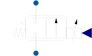
The component PropValve22PT2 is a model of a 2-way proportional valve where the stroke follows the input signal with a 2nd order delay.
For a positive stroke (right position), the flow is scaled in proportion to the input signal starting from 0 to Input value for 100 % open with nominal flow (as given by Nominal volume flow/Nominal pressure difference) corresponding to an input value of Input value for 100 % open.
The valve stroke can be shifted by Valve edge relative overlap. In accordance with common valve parameters a negative overlap will open the valve edge.
The default relationship between input signal and flow rate of the metering edge is linear, but can be changed through the use of a 1D look-up table. The look-up table is provided either manually or by importing a text file. If the parameter Table is provided by file is set to false, the manually entered datapoints from Manually provided look-up table will be used. If it is set to true, the table Table name on file from the file File where look-up table is stored will be utilized.
The text file must follow a specific syntax such that it can be read by Modelica. The input values as well as the output values must lie within the range from 0 to 1. An output value of 1 (100 %) corresponds to a fully-opened metering edge. An example for a properly formatted text file with two tables is given in the figure below:
A table is declared by its datatype (e. g. double), followed by the table name (e. g. tab1) and its dimensions in brackets (e. g. (5,2)). As can be seen, multiple tables can be defined in the same text file. The table declaration is followed by the actual data. The first column of the table represents the input of the 1D table, whereas the second column lists the corresponding output values. The input values of the table must be in increasing order. The component interpolates linearly between the listed input values. More information regarding the format of tables can be found at CombiTable1D.
Extends from HydraulicsByFluidon.Components.Valves.Base.PartialValve22, HydraulicsByFluidon.Components.Valves.Base.PartialValveControlSignal_x2, and HydraulicsByFluidon.Components.Valves.Base.PartialValveProp_x2.
| Type | Name | Default | Description |
|---|---|---|---|
Real | inputMax | 10 | Input value for 100 % open |
AngularFrequency | angFreq | 2 * Modelica.Constants.pi * 50 | Angular frequency |
DampingCoefficient | damping | 0.7 | Damping |
TimeAging | vMax | 100 | max. Velocity |
TimeAging | vMin | -100 | min. Velocity |
Boolean | enableStrokeOut | false | Enable Stroke Output |
VolumeFlowRate | NominalVolumeFlow | 5e-4 | Nominal volume flow |
Pressure | NominalPressureDifference | 500000 | Nominal pressure difference |
Density | ReferenceDensity | 860 | Reference density for volume flow and pressure difference |
DimensionlessRatio | Overlap | 0 | Valve edge relative overlap |
Boolean | tableFromFile | false | Table is provided by file |
String | fileName | "NoFile" | File where look-up table is stored |
String | tableName | "NoTable" | Table name on file |
Real | manualTable[:,:] | [0,0; 1,1] | Manually provided look-up table |
VolumeFlowRate | ZeroVolumeFlow | 0 | Volume flow due to leakage |
Pressure | ZeroFlowPressureDifference | 500000 | Pressure difference for leakage flow |
Volume | deadVolume | 1e-6 | Dead volume at ports |
Init | initType | Modelica.Blocks.Types.Init.InitialState | Type of initialization (1: no init, 2: steady state, 3/4: initial output) |
| Type | Name | Description |
|---|---|---|
FluidPort | portA | Hydraulic port A |
FluidPort | portP | Hydraulic port P |
output RealOutput | valveStrokeOut | Valve Stroke |
input RealInput | Input | Set value of valve position |
 Model HydraulicsByFluidon.Components.Valves.DirectionalValves.PropValve22PT2TableAx
The component PropValve22PT2TableAx is a model of a 2-way proportional valve where the stroke follows the input signal with a 2nd order delay.
The parameterization of the meetering edge is done by providing the Flow coefficient alphaD and a look-up table of the Cross-sectional area as a function of the input signal. Further information regarding the formatting of the look-up table can be found in the documentation of the component ResistorTableAx.
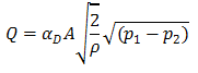
For a positive stroke, the cross-sectional area of the valve's meetering edge is given as a function of the input signal through a look-up table starting from 0 to maximum area (the cross-sectional area of the valve when it is completely open). The cross-sectional area must be given in m^2. The flow is then calculated based on Flow coefficient alphaD, Cross-sectional area, density of the fluid and pressure difference between the two edges of the valve, according to the formula given below:
The valve stroke can be shifted by Relative overlap general. In accordance with common valve parameters a negative overlap will open the valve edge.
Extends from HydraulicsByFluidon.Components.Valves.Base.PartialValve22TableAx, HydraulicsByFluidon.Components.Valves.Base.PartialValveControlSignal_x2, and HydraulicsByFluidon.Components.Valves.Base.PartialValveProp_x2.
| Type | Name | Default | Description |
|---|---|---|---|
Real | inputMax | 10 | Input value for 100 % open |
AngularFrequency | angFreq | 2 * Modelica.Constants.pi * 50 | Angular frequency |
DampingCoefficient | damping | 0.7 | Damping |
TimeAging | vMax | 100 | max. Velocity |
TimeAging | vMin | -100 | min. Velocity |
Boolean | enableStrokeOut | false | Enable Stroke Output |
DimensionlessRatio | Overlap | 0 | Valve edge relative overlap |
Real | alphaD | 0.6 | Flow coefficient alphaD |
Boolean | tableFromFile | false | Table is provided by file |
String | fileName | "NoFile" | File where look-up table is stored |
String | tableName | "NoTable" | Table name on file |
Real | manualTable[:,:] | [0,0; 1,2.444e-5] | Manually provided look-up table |
Volume | deadVolume | 1e-6 | Dead volume at ports |
Init | initType | Modelica.Blocks.Types.Init.InitialState | Type of initialization (1: no init, 2: steady state, 3/4: initial output) |
| Type | Name | Description |
|---|---|---|
FluidPort | portA | Hydraulic port A |
FluidPort | portP | Hydraulic port P |
output RealOutput | valveStrokeOut | Valve Stroke |
input RealInput | Input | Set value of valve position |
 Model HydraulicsByFluidon.Components.Valves.DirectionalValves.PropValve22PT2TableQpx
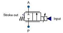
The component PropValve22PT2TableQpx is a model of a 2-way proportional valve where the stroke follows the input signal with a 2nd order delay.
The hydraulic parameterization of the meetering edge is done by providing a look-up table of the flow rate as a function of the pressure drop and the input signal. Further information regarding the formatting of the look-up table can be found in the documentation of the component ResistorTableQpx.
For a positive stroke, the flow rate is increased with increasing input signal starting from 0 to Input value for 100 % open with maximum flow corresponding to an input value of Input value for 100 % open.
The valve stroke can be shifted by Relative overlap general. In accordance with common valve parameters a negative overlap will open the valve edge.
Extends from HydraulicsByFluidon.Components.Valves.Base.PartialValve22TableQpx, HydraulicsByFluidon.Components.Valves.Base.PartialValveControlSignal_x2, and HydraulicsByFluidon.Components.Valves.Base.PartialValveProp_x2.
| Type | Name | Default | Description |
|---|---|---|---|
Real | inputMax | 10 | Input value for 100 % open |
AngularFrequency | angFreq | 2 * Modelica.Constants.pi * 50 | Angular frequency |
DampingCoefficient | damping | 0.7 | Damping |
TimeAging | vMax | 100 | max. Velocity |
TimeAging | vMin | -100 | min. Velocity |
Boolean | enableStrokeOut | false | Enable Stroke Output |
DimensionlessRatio | Overlap | 0 | Valve edge relative overlap |
Density | ReferenceDensity | 860 | Reference density |
String | fileName | "NoFile" | File where look-up table is stored |
String | tableName | "NoTable" | Table name on file |
Volume | deadVolume | 1e-6 | Dead volume at ports |
Init | initType | Modelica.Blocks.Types.Init.InitialState | Type of initialization (1: no init, 2: steady state, 3/4: initial output) |
| Type | Name | Description |
|---|---|---|
FluidPort | portA | Hydraulic port A |
FluidPort | portP | Hydraulic port P |
output RealOutput | valveStrokeOut | Valve Stroke |
input RealInput | Input | Set value of valve position |
 Model HydraulicsByFluidon.Components.Valves.DirectionalValves.PropValve33PT2
The component PropValve33PT2 is a model of a 3-way proportional valve where the stroke follows the input signal with a 2nd order delay.
For a positive stroke (right position), the flow is scaled in proportion to the input signal starting from 0 to Input value for 100 % open with nominal flow (as given by Nominal volume flow/Nominal pressure difference) corresponding to an input value of Input value for 100 % open. In case of a negative stroke (left position) the same applies for input from 0 to -Input value for 100 % open.
The valve stroke can be shifted by Valve edge general relative overlap. In accordance with common valve parameters a negative overlap will open the valve edge. Valve edge general relative overlap is applied to all valve edges simultaneously. If at least one of the edge-specific values, e. g. Valve edge PA relative overlap is set to a value different from 0, then Valve edge general relative overlap is ignored and the individual overlaps are used.
The default relationship between input signal and flow rate of the metering edge is linear, but can be changed through the use of a 1D look-up table. The look-up table is provided either manually or by importing a text file. If the parameter Table is provided by file is set to false, the manually entered datapoints from Manually provided look-up table will be used. If it is set to true, the table Table name on file from the file File where look-up table is stored will be utilized.
The text file must follow a specific syntax such that it can be read by Modelica. The input values as well as the output values must lie within the range from 0 to 1. An output value of 1 (100 %) corresponds to a fully-opened metering edge. An example for a properly formatted text file with two tables is given in the figure below:
A table is declared by its datatype (e. g. double), followed by the table name (e. g. tab1) and its dimensions in brackets (e. g. (5,2)). As can be seen, multiple tables can be defined in the same text file. The table declaration is followed by the actual data. The first column of the table represents the input of the 1D table, whereas the second column lists the corresponding output values. The input values of the table must be in increasing order. The component interpolates linearly between the listed input values. More information regarding the format of tables can be found at CombiTable1D.
Extends from HydraulicsByFluidon.Components.Valves.Base.PartialValve33, HydraulicsByFluidon.Components.Valves.Base.PartialValveControlSignal_x3, and HydraulicsByFluidon.Components.Valves.Base.PartialValveProp_x3.
| Type | Name | Default | Description |
|---|---|---|---|
Real | inputMax | 10 | Input value for 100 % open |
AngularFrequency | angFreq | 2 * Modelica.Constants.pi * 50 | Angular frequency |
DampingCoefficient | damping | 0.7 | Damping |
TimeAging | vMax | 100 | max. Velocity |
TimeAging | vMin | -100 | min. Velocity |
Boolean | enableStrokeOut | false | Enable Stroke Output |
VolumeFlowRate | NominalVolumeFlow | 5e-4 | Nominal volume flow |
Pressure | NominalPressureDifference | 500000 | Nominal pressure difference |
Density | ReferenceDensity | 860 | Reference density for volume flow and pressure difference |
DimensionlessRatio | Overlap | 0 | Valve edge general relative overlap |
DimensionlessRatio | OverlapPA | 0 | Valve edge PA relative overlap |
DimensionlessRatio | QFactorPA | 1 | Factor for edge PA specific flow adjustment |
Boolean | tableFromFilePA | false | Table is provided by file |
String | fileNamePA | "NoFile" | File where look-up table is stored |
String | tableNamePA | "NoTable" | Table name on file |
Real | manualTablePA[:,:] | [-1,0; 0,0; 1,1] | Manually provided look-up table |
DimensionlessRatio | OverlapAT | 0 | Valve edge AT relative overlap |
DimensionlessRatio | QFactorAT | 1 | Factor for edge AT specific flow adjustment |
Boolean | tableFromFileAT | false | Table is provided by file |
String | fileNameAT | "NoFile" | File where look-up table is stored |
String | tableNameAT | "NoTable" | Table name on file |
Real | manualTableAT[:,:] | [-1,0; 0,0; 1,1] | Manually provided look-up table |
VolumeFlowRate | ZeroVolumeFlow | 0 | Volume flow due to leakage |
Pressure | ZeroFlowPressureDifference | 500000 | Pressure difference for leakage flow |
Volume | deadVolume | 1e-6 | Dead volume at ports |
Init | initType | Modelica.Blocks.Types.Init.InitialState | Type of initialization (1: no init, 2: steady state, 3/4: initial output) |
| Type | Name | Description |
|---|---|---|
FluidPort | portA | Hydraulic port A |
FluidPort | portP | Hydraulic port P |
FluidPort | portT | Hydraulic port T |
output RealOutput | valveStrokeOut | Valve Stroke |
input RealInput | Input | Set value of valve position |
 Model HydraulicsByFluidon.Components.Valves.DirectionalValves.PropValve33PT2TableAx
The component PropValve33PT2TableAx is a model of a 3-way proportional valve where the stroke follows the input signal with a 2nd order delay.
The parameterization of the valve is done by providing the Flow coefficient alphaD and a look-up table of the Cross-sectional area as a function of the input signal. Each of the two meetering edges is parameterised with a separate look-up table and a Flow coefficient alphaD given by the user. Further information regarding the formatting of the look-up table can be found in the documentation of the component ResistorTableAx. Unlike the Resistor component, the look-up table for valve edges is declared for the input range from -1 to 1.
For a positive and negative stroke, the cross-sectional area of the valve's meetering edge is given as a function of the input signal through a look-up table starting from 0 to maximum area (the cross-sectional area of the valve edge when it is completely open). The cross-sectional area must be given in m^2. The flow is then calculated based on Flow coefficient alphaD, Cross-sectional area, density of the fluid and pressure difference between the two edges of the valve, according to the formula given below:
The valve stroke can be shifted by Relative overlap general. In accordance with common valve parameters a negative overlap will open the valve edge. Relative overlap general is applied to all valve edges simultaneously. If at least one of the edge-specific values, e. g. Relative overlap PA or -AT is set to a value different from 0, then the Relative overlap general is ignored and the individual overlaps are used.
Extends from HydraulicsByFluidon.Components.Valves.Base.PartialValve33TableAx, HydraulicsByFluidon.Components.Valves.Base.PartialValveControlSignal_x3, and HydraulicsByFluidon.Components.Valves.Base.PartialValveProp_x3.
| Type | Name | Default | Description |
|---|---|---|---|
Real | inputMax | 10 | Input value for 100 % open |
AngularFrequency | angFreq | 2 * Modelica.Constants.pi * 50 | Angular frequency |
DampingCoefficient | damping | 0.7 | Damping |
TimeAging | vMax | 100 | max. Velocity |
TimeAging | vMin | -100 | min. Velocity |
Boolean | enableStrokeOut | false | Enable Stroke Output |
DimensionlessRatio | Overlap | 0 | Valve edge general relative overlap |
DimensionlessRatio | OverlapPA | 0 | Valve edge PA relative overlap |
Real | alphaDPA | 0.6 | Flow coefficient alphaD |
Boolean | tableFromFilePA | false | Table is provided by file |
String | fileNamePA | "NoFile" | File where look-up table is stored |
String | tableNamePA | "NoTable" | Table name on file |
Real | manualTablePA[:,:] | [-1,0; 0,0; 1,2.444e-5] | Manually provided look-up table |
DimensionlessRatio | OverlapAT | 0 | Valve edge AT relative overlap |
Real | alphaDAT | 0.6 | Flow coefficient alphaD |
Boolean | tableFromFileAT | false | Table is provided by file |
String | fileNameAT | "NoFile" | File where look-up table is stored |
String | tableNameAT | "NoTable" | Table name on file |
Real | manualTableAT[:,:] | [-1,0; 0,0; 1,2.444e-5] | Manually provided look-up table |
Volume | deadVolume | 1e-6 | Dead volume at ports |
Init | initType | Modelica.Blocks.Types.Init.InitialState | Type of initialization (1: no init, 2: steady state, 3/4: initial output) |
| Type | Name | Description |
|---|---|---|
FluidPort | portA | Hydraulic port A |
FluidPort | portP | Hydraulic port P |
FluidPort | portT | Hydraulic port T |
output RealOutput | valveStrokeOut | Valve Stroke |
input RealInput | Input | Set value of valve position |
 Model HydraulicsByFluidon.Components.Valves.DirectionalValves.PropValve33PT2TableQpx
The component PropValve33PT2TableQpx is a model of a 3-way proportional valve where the stroke follows the input signal with a 2nd order delay.
The hydraulic parameterization of the valve is done by providing a look-up table of the flow rate as a function of the pressure drop and the input signal. Each of the two meetering edges is parameterised with a separate look-up table given by the user. Further information regarding the formatting of the look-up table can be found in the documentation of the component ResistorTableQpx. Unlike the Resistor component, the look-up table for valve edges is declared for the input range from -1 to 1.
For a positive stroke (right position) the flow is function of input signal (starting from 0 to Input value for 100 % open) and the pressure difference across the valve edge. In case of a negative stroke (left position) the same applies for input from 0 to -Input value for 100 % open.
The valve stroke can be shifted by Relative overlap general. In accordance with common valve parameters a negative overlap will open the valve edge. Relative overlap general is applied to all valve edges simultaneously. If at least one of the edge-specific values, e. g. Relative overlap PA or -AT is set to a value different from 0, then the Relative overlap general is ignored and the individual overlaps are used.
Extends from HydraulicsByFluidon.Components.Valves.Base.PartialValve33TableQpx, HydraulicsByFluidon.Components.Valves.Base.PartialValveControlSignal_x3, and HydraulicsByFluidon.Components.Valves.Base.PartialValveProp_x3.
| Type | Name | Default | Description |
|---|---|---|---|
Real | inputMax | 10 | Input value for 100 % open |
AngularFrequency | angFreq | 2 * Modelica.Constants.pi * 50 | Angular frequency |
DampingCoefficient | damping | 0.7 | Damping |
TimeAging | vMax | 100 | max. Velocity |
TimeAging | vMin | -100 | min. Velocity |
Boolean | enableStrokeOut | false | Enable Stroke Output |
DimensionlessRatio | Overlap | 0 | Valve edge general relative overlap |
Density | ReferenceDensity | 860 | Reference density |
DimensionlessRatio | OverlapPA | 0 | Valve edge PA relative overlap |
String | fileNamePA | "NoFile" | File where look-up table is stored |
String | tableNamePA | "NoTable" | Table name on file |
DimensionlessRatio | OverlapAT | 0 | Valve edge AT relative overlap |
String | fileNameAT | "NoFile" | File where look-up table is stored |
String | tableNameAT | "NoTable" | Table name on file |
Volume | deadVolume | 1e-6 | Dead volume at ports |
Init | initType | Modelica.Blocks.Types.Init.InitialState | Type of initialization (1: no init, 2: steady state, 3/4: initial output) |
| Type | Name | Description |
|---|---|---|
FluidPort | portA | Hydraulic port A |
FluidPort | portP | Hydraulic port P |
FluidPort | portT | Hydraulic port T |
output RealOutput | valveStrokeOut | Valve Stroke |
input RealInput | Input | Set value of valve position |
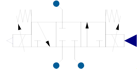
 Model HydraulicsByFluidon.Components.Valves.DirectionalValves.PropValve43PT2
The component PropValve43PT2 is a model of a 3-way proportional valve where the stroke follows the input signal with a 2nd order delay.
For a positive stroke (right position), the flow is scaled in proportion to the input signal starting from 0 to Input value for 100 % open with nominal flow (as given by Nominal volume flow/Nominal pressure difference) corresponding to an input value of Input value for 100 % open. In case of a negative stroke (left position) the same applies for input from 0 to -Input value for 100 % open.
The valve stroke can be shifted by Valve edge general relative overlap. In accordance with common valve parameters a negative overlap will open the valve edge. Valve edge general relative overlap is applied to all valve edges simultaneously. If at least one of the edge-specific values, e. g. Valve edge PA relative overlap is set to a value different from 0, then Valve edge general relative overlap is ignored and the individual overlaps are used.
The default relationship between input signal and flow rate of the metering edge is linear, but can be changed through the use of a 1D look-up table. The look-up table is provided either manually or by importing a text file. If the parameter Table is provided by file is set to false, the manually entered datapoints from Manually provided look-up table will be used. If it is set to true, the table Table name on file from the file File where look-up table is stored will be utilized.
The text file must follow a specific syntax such that it can be read by Modelica. The input values as well as the output values must lie within the range from 0 to 1. An output value of 1 (100 %) corresponds to a fully-opened metering edge. An example for a properly formatted text file with two tables is given in the figure below:
A table is declared by its datatype (e. g. double), followed by the table name (e. g. tab1) and its dimensions in brackets (e. g. (5,2)). As can be seen, multiple tables can be defined in the same text file. The table declaration is followed by the actual data. The first column of the table represents the input of the 1D table, whereas the second column lists the corresponding output values. The input values of the table must be in increasing order. The component interpolates linearly between the listed input values. More information regarding the format of tables can be found at CombiTable1D.
Extends from HydraulicsByFluidon.Components.Valves.Base.PartialValve43, HydraulicsByFluidon.Components.Valves.Base.PartialValveControlSignal_x3, and HydraulicsByFluidon.Components.Valves.Base.PartialValveProp_x3.
| Type | Name | Default | Description |
|---|---|---|---|
Real | inputMax | 10 | Input value for 100 % open |
AngularFrequency | angFreq | 2 * Modelica.Constants.pi * 50 | Angular frequency |
DampingCoefficient | damping | 0.7 | Damping |
TimeAging | vMax | 100 | max. Velocity |
TimeAging | vMin | -100 | min. Velocity |
Boolean | enableStrokeOut | false | Enable Stroke Output |
VolumeFlowRate | NominalVolumeFlow | 5e-4 | Nominal volume flow |
Pressure | NominalPressureDifference | 500000 | Nominal pressure difference |
Density | ReferenceDensity | 860 | Reference density for volume flow and pressure difference |
DimensionlessRatio | Overlap | 0 | Valve edge general relative overlap |
DimensionlessRatio | OverlapPA | 0 | Valve edge PA relative overlap |
DimensionlessRatio | OverlapPB | 0 | Valve edge PB relative overlap |
DimensionlessRatio | OverlapAT | 0 | Valve edge AT relative overlap |
DimensionlessRatio | OverlapBT | 0 | Valve edge BT relative overlap |
VolumeFlowRate | ZeroVolumeFlow | 0 | Volume flow due to leakage |
Pressure | ZeroFlowPressureDifference | 500000 | Pressure difference for leakage flow |
Real | QFactorPA | 1 | Factor for edge PA specific flow adjustment |
Boolean | tableFromFilePA | false | Table is provided by file |
String | fileNamePA | "NoFile" | File where look-up table is stored |
String | tableNamePA | "NoTable" | Table name on file |
Real | manualTablePA[:,:] | [-1,0; 0,0; 1,1] | Manually provided look-up table |
Real | QFactorPB | 1 | Factor for edge PB specific flow adjustment |
Boolean | tableFromFilePB | false | Table is provided by file |
String | fileNamePB | "NoFile" | File where look-up table is stored |
String | tableNamePB | "NoTable" | Table name on file |
Real | manualTablePB[:,:] | [-1,0; 0,0; 1,1] | Manually provided look-up table |
Real | QFactorAT | 1 | Factor for edge AT specific flow adjustment |
Boolean | tableFromFileAT | false | Table is provided by file |
String | fileNameAT | "NoFile" | File where look-up table is stored |
String | tableNameAT | "NoTable" | Table name on file |
Real | manualTableAT[:,:] | [-1,0; 0,0; 1,1] | Manually provided look-up table |
Real | QFactorBT | 1 | Factor for edge BT specific flow adjustment |
Boolean | tableFromFileBT | false | Table is provided by file |
String | fileNameBT | "NoFile" | File where look-up table is stored |
String | tableNameBT | "NoTable" | Table name on file |
Real | manualTableBT[:,:] | [-1,0; 0,0; 1,1] | Manually provided look-up table |
Volume | deadVolume | 1e-6 | Dead volume at ports |
Init | initType | Modelica.Blocks.Types.Init.InitialState | Type of initialization (1: no init, 2: steady state, 3/4: initial output) |
| Type | Name | Description |
|---|---|---|
FluidPort | portA | Hydraulic port A |
FluidPort | portB | Hydraulic port B |
FluidPort | portP | Hydraulic port P |
FluidPort | portT | Hydraulic port T |
output RealOutput | valveStrokeOut | Valve Stroke |
input RealInput | Input | Set value of valve position |
 Model HydraulicsByFluidon.Components.Valves.DirectionalValves.PropValve43PT2TableAx
The component PropValve43PT2TableAx is a model of a 3-way proportional valve where the stroke follows the input signal with a 2nd order delay.
The parameterization of the valve is done by providing the Flow coefficient alphaD and a look-up table of the Cross-sectional area as a function of the input signal. Each of the four meetering edges is parameterised with a separate look-up table and a Flow coefficient alphaD given by the user. Further information regarding the formatting of the look-up table can be found in the documentation of the component ResistorTableAx. Unlike the Resistor component, the look-up table for valve edges is declared for the input range from -1 to 1.
For a positive and negative stroke, the cross-sectional area of the valve's meetering edge is given as a function of the input signal through a look-up table starting from 0 to maximum area (the cross-sectional area of the valve edge when it is completely open). The cross-sectional area must be given in m^2. The flow is then calculated based on Flow coefficient alphaD, Cross-sectional area, density of the fluid and pressure difference between the two edges of the valve, according to the formula given below:
The valve stroke can be shifted by Relative overlap general. In accordance with common valve parameters a negative overlap will open the valve edge. Relative overlap general is applied to all valve edges simultaneously. If at least one of the edge-specific values, e. g. Relative overlap PA or -AT is set to a value different from 0, then the Relative overlap general is ignored and the individual overlaps are used.
Extends from HydraulicsByFluidon.Components.Valves.Base.PartialValve43TableAx, HydraulicsByFluidon.Components.Valves.Base.PartialValveControlSignal_x3, and HydraulicsByFluidon.Components.Valves.Base.PartialValveProp_x3.
| Type | Name | Default | Description |
|---|---|---|---|
Real | inputMax | 10 | Input value for 100 % open |
AngularFrequency | angFreq | 2 * Modelica.Constants.pi * 50 | Angular frequency |
DampingCoefficient | damping | 0.7 | Damping |
TimeAging | vMax | 100 | max. Velocity |
TimeAging | vMin | -100 | min. Velocity |
Boolean | enableStrokeOut | false | Enable Stroke Output |
DimensionlessRatio | Overlap | 0 | Valve edge general relative overlap |
DimensionlessRatio | OverlapPA | 0 | Valve edge PA relative overlap |
DimensionlessRatio | OverlapPB | 0 | Valve edge PB relative overlap |
DimensionlessRatio | OverlapAT | 0 | Valve edge AT relative overlap |
DimensionlessRatio | OverlapBT | 0 | Valve edge BT relative overlap |
Real | alphaDPA | 0.6 | Flow coefficient alphaD |
Boolean | tableFromFilePA | false | Table is provided by file |
String | fileNamePA | "NoFile" | File where look-up table is stored |
String | tableNamePA | "NoTable" | Table name on file |
Real | manualTablePA[:,:] | [-1,0; 0,0; 1,2.444e-5] | Manually provided look-up table |
Real | alphaDPB | 0.6 | Flow coefficient alphaD |
Boolean | tableFromFilePB | false | Table is provided by file |
String | fileNamePB | "NoFile" | File where look-up table is stored |
String | tableNamePB | "NoTable" | Table name on file |
Real | manualTablePB[:,:] | [-1,0; 0,0; 1,2.444e-5] | Manually provided look-up table |
Real | alphaDAT | 0.6 | Flow coefficient alphaD |
Boolean | tableFromFileAT | false | Table is provided by file |
String | fileNameAT | "NoFile" | File where look-up table is stored |
String | tableNameAT | "NoTable" | Table name on file |
Real | manualTableAT[:,:] | [-1,0; 0,0; 1,2.444e-5] | Manually provided look-up table |
Volume | deadVolume | 1e-6 | Dead volume at ports |
Real | alphaDBT | 0.6 | Flow coefficient alphaD |
Boolean | tableFromFileBT | false | Table is provided by file |
String | fileNameBT | "NoFile" | File where look-up table is stored |
String | tableNameBT | "NoTable" | Table name on file |
Real | manualTableBT[:,:] | [-1,0; 0,0; 1,2.444e-5] | Manually provided look-up table |
Init | initType | Modelica.Blocks.Types.Init.InitialState | Type of initialization (1: no init, 2: steady state, 3/4: initial output) |
| Type | Name | Description |
|---|---|---|
FluidPort | portA | Hydraulic port A |
FluidPort | portB | Hydraulic port B |
FluidPort | portP | Hydraulic port P |
FluidPort | portT | Hydraulic port T |
output RealOutput | valveStrokeOut | Valve Stroke |
input RealInput | Input | Set value of valve position |
 Model HydraulicsByFluidon.Components.Valves.DirectionalValves.PropValve43PT2TableQpx
The component PropValve43PT2TableQpx is a model of a 3-way proportional valve where the stroke follows the input signal with a 2nd order delay.
The hydraulic parameterization of the valve is done by providing a look-up table of the flow rate as a function of the pressure drop and the input signal. Each of the four meetering edges is parameterised with a separate look-up table given by the user. Further information regarding the formatting of the look-up table can be found in the documentation of the component ResistorTableQpx. Unlike the Resistor component, the look-up table for valve edges is declared for the input range from -1 to 1.
For a positive stroke (right position) the flow is function of input signal (starting from 0 to Input value for 100 % open) and the pressure difference across the valve edge. In case of a negative stroke (left position) the same applies for input from 0 to -Input value for 100 % open.
The valve stroke can be shifted by Relative overlap general. In accordance with common valve parameters a negative overlap will open the valve edge. Relative overlap general is applied to all valve edges simultaneously. If at least one of the edge-specific values, e. g. Relative overlap PA or -AT is set to a value different from 0, then the Relative overlap general is ignored and the individual overlaps are used.
Extends from HydraulicsByFluidon.Components.Valves.Base.PartialValve43TableQpx, HydraulicsByFluidon.Components.Valves.Base.PartialValveControlSignal_x3, and HydraulicsByFluidon.Components.Valves.Base.PartialValveProp_x3.
| Type | Name | Default | Description |
|---|---|---|---|
Real | inputMax | 10 | Input value for 100 % open |
AngularFrequency | angFreq | 2 * Modelica.Constants.pi * 50 | Angular frequency |
DampingCoefficient | damping | 0.7 | Damping |
TimeAging | vMax | 100 | max. Velocity |
TimeAging | vMin | -100 | min. Velocity |
Boolean | enableStrokeOut | false | Enable Stroke Output |
Density | ReferenceDensity | 860 | Reference density |
DimensionlessRatio | Overlap | 0 | Valve edge general relative overlap |
DimensionlessRatio | OverlapPA | 0 | Valve edge PA relative overlap |
DimensionlessRatio | OverlapPB | 0 | Valve edge PB relative overlap |
DimensionlessRatio | OverlapAT | 0 | Valve edge AT relative overlap |
DimensionlessRatio | OverlapBT | 0 | Valve edge BT relative overlap |
String | fileNamePA | "NoFile" | File where look-up table is stored |
String | tableNamePA | "NoTable" | Table name on file |
String | fileNamePB | "NoFile" | File where look-up table is stored |
String | tableNamePB | "NoTable" | Table name on file |
String | fileNameAT | "NoFile" | File where look-up table is stored |
String | tableNameAT | "NoTable" | Table name on file |
String | fileNameBT | "NoFile" | File where look-up table is stored |
String | tableNameBT | "NoTable" | Table name on file |
Volume | deadVolume | 1e-6 | Dead volume at ports |
Init | initType | Modelica.Blocks.Types.Init.InitialState | Type of initialization (1: no init, 2: steady state, 3/4: initial output) |
| Type | Name | Description |
|---|---|---|
FluidPort | portA | Hydraulic port A |
FluidPort | portB | Hydraulic port B |
FluidPort | portP | Hydraulic port P |
FluidPort | portT | Hydraulic port T |
output RealOutput | valveStrokeOut | Valve Stroke |
input RealInput | Input | Set value of valve position |
 Model HydraulicsByFluidon.Components.Valves.DirectionalValves.PropValve63PT2
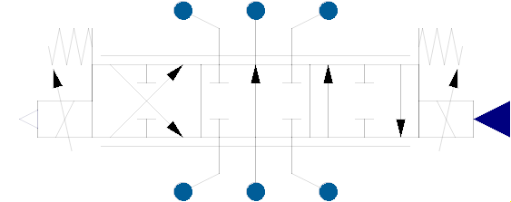
The component PropValve63PT2 is a model of a 3-way proportional valve where the stroke follows the input signal with a 2nd order delay.
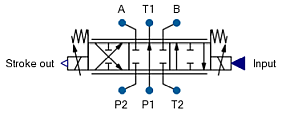
For a positive stroke (right position) the flow is scaled proportional to the input signal starting from 0 to Input value for 100 % open with nominal flow (as given by Nominal volume flow/Nominal pressure difference) corresponding to an input value of Input value for 100 % open. In case of a negative stroke (left position) the same applies for input from 0 to -Input value for 100 % open.
The valve stroke can be shifted by Valve edge general relative overlap. In accordance with common valve parameters a negative overlap will open the valve edge. Valve edge general relative overlap is applied to all valve edges simultaneously. If at least one of the edge-specific values, e. g. Valve edge PA relative overlap is set to a value different from 0, then Valve edge general relative overlap is ignored and the individual overlaps are used.
The default relationship between input signal and flow rate of the metering edge is linear, but can be changed through the use of a 1D look-up table. The look-up table is provided either manually or by importing a text file. If the parameter Table is provided by file is set to false, the manually entered datapoints from Manually provided look-up table will be used. If it is set to true, the table Table name on file from the file File where look-up table is stored will be utilized.
The text file must follow a specific syntax such that it can be read by Modelica. The input values as well as the output values must lie within the range from 0 to 1. An output value of 1 (100 %) corresponds to a fully-opened metering edge. An example for a properly formatted text file with two tables is given in the figure below:
A table is declared by its datatype (e. g. double), followed by the table name (e. g. tab1) and its dimensions in brackets (e. g. (5,2)). As can be seen, multiple tables can be defined in the same text file. The table declaration is followed by the actual data. The first column of the table represents the input of the 1D table, whereas the second column lists the corresponding output values. The input values of the table must be in increasing order. The component interpolates linearly between the listed input values. More information regarding the format of tables can be found at CombiTable1D.
Extends from HydraulicsByFluidon.Components.Valves.Base.PartialValve63, HydraulicsByFluidon.Components.Valves.Base.PartialValveControlSignal_63, and HydraulicsByFluidon.Components.Valves.Base.PartialValveProp_63.
| Type | Name | Default | Description |
|---|---|---|---|
Real | inputMax | 10 | Input value for 100 % open |
AngularFrequency | angFreq | 2 * Modelica.Constants.pi * 50 | Angular frequency |
DampingCoefficient | damping | 0.7 | Damping |
TimeAging | vMax | 100 | max. Velocity |
TimeAging | vMin | -100 | min. Velocity |
Boolean | enableStrokeOut | false | Enable Stroke Output |
VolumeFlowRate | NominalVolumeFlow | 5e-4 | Nominal volume flow |
Pressure | NominalPressureDifference | 500000 | Nominal pressure difference |
Density | ReferenceDensity | 860 | Reference density for volume flow and pressure difference |
DimensionlessRatio | Overlap | 0 | Valve edge general relative overlap |
DimensionlessRatio | OverlapP1T1 | 0 | Valve edge P1T1 relative overlap |
DimensionlessRatio | OverlapP2A | 0 | Valve edge P2A relative overlap |
DimensionlessRatio | OverlapP2B | 0 | Valve edge P2B relative overlap |
DimensionlessRatio | OverlapAT2 | 0 | Valve edge AT2 relative overlap |
DimensionlessRatio | OverlapBT2 | 0 | Valve edge BT2 relative overlap |
VolumeFlowRate | ZeroVolumeFlow | 0 | Volume flow due to leakage |
Pressure | ZeroFlowPressureDifference | 500000 | Pressure difference for leakage flow |
Real | QFactorP1T1 | 1 | Factor for edge P1T1 specific flow adjustment |
Boolean | tableFromFileP1T1 | false | Table is provided by file |
String | fileNameP1T1 | "NoFile" | File where look-up table is stored |
String | tableNameP1T1 | "NoTable" | Table name on file |
Real | manualTableP1T1[:,:] | [0,0; 1,1] | Manually provided look-up table |
Real | QFactorP2A | 1 | Factor for edge P2A specific flow adjustment |
Boolean | tableFromFileP2A | false | Table is provided by file |
String | fileNameP2A | "NoFile" | File where look-up table is stored |
String | tableNameP2A | "NoTable" | Table name on file |
Real | manualTableP2A[:,:] | [0,0; 1,1] | Manually provided look-up table |
Real | QFactorP2B | 1 | Factor for edge P2B specific flow adjustment |
Boolean | tableFromFileP2B | false | Table is provided by file |
String | fileNameP2B | "NoFile" | File where look-up table is stored |
String | tableNameP2B | "NoTable" | Table name on file |
Real | manualTableP2B[:,:] | [0,0; 1,1] | Manually provided look-up table |
Real | QFactorAT2 | 1 | Factor for edge AT2 specific flow adjustment |
Boolean | tableFromFileAT2 | false | Table is provided by file |
String | fileNameAT2 | "NoFile" | File where look-up table is stored |
String | tableNameAT2 | "NoTable" | Table name on file |
Real | manualTableAT2[:,:] | [0,0; 1,1] | Manually provided look-up table |
Real | QFactorBT2 | 1 | Factor for edge BT2 specific flow adjustment |
Boolean | tableFromFileBT2 | false | Table is provided by file |
String | fileNameBT2 | "NoFile" | File where look-up table is stored |
String | tableNameBT2 | "NoTable" | Table name on file |
Real | manualTableBT2[:,:] | [0,0; 1,1] | Manually provided look-up table |
Volume | deadVolume | 1e-6 | Dead volume at ports |
Init | initType | Modelica.Blocks.Types.Init.InitialState | Type of initialization (1: no init, 2: steady state, 3/4: initial output) |
| Type | Name | Description |
|---|---|---|
FluidPort | portP1 | Hydraulic port P1 |
FluidPort | portT1 | Hydraulic port T1 |
FluidPort | portP2 | Hydraulic port P2 |
FluidPort | portT2 | Hydraulic port T2 |
FluidPort | portA | Hydraulic port A |
FluidPort | portB | Hydraulic port B |
output RealOutput | valveStrokeOut | Valve Stroke |
input RealInput | Input | Set value of valve position |