 Package Modelica.Electrical.Digital.Interfaces
Basic definitions
Package Modelica.Electrical.Digital.Interfaces
This package contains basic definitions: Type definitions of Logic and Strength, interface definitions (connectors) for digital electrical components, and partial models for connection patterns which are often used.
Extends from Modelica.Icons.InterfacesPackage (Icon for packages containing interfaces).
| Name | Description |
|---|---|
DigitalInput | Input DigitalSignal as connector |
DigitalOutput | Output DigitalSignal as connector |
DigitalSignal | Digital port (both input/output possible) |
Logic | Logic values and their coding according to IEEE 1164 STD_ULOGIC type |
MemoryBase | Base model for memory elements |
MIMO | Multiple input - multiple output |
MISO | Multiple input - single output |
SISO | Single input, single output |
Strength | Output strengths of registers |
UX01 | 4-valued subtype of IEEE 1164 STD_ULOGIC type |
 Enumeration Modelica.Electrical.Digital.Interfaces.Logic
Code Table:
| Logic value | Meaning |
| 'U' | Uninitialized |
| 'X' | Forcing Unknown |
| '0' | Forcing 0 |
| '1' | Forcing 1 |
| 'Z' | High Impedance |
| 'W' | Weak Unknown |
| 'L' | Weak 0 |
| 'H' | Weak 1 |
| '-' | Do not care |
| Name | Description |
|---|---|
'U' | U Uninitialized |
'X' | X Forcing Unknown |
'0' | 0 Forcing 0 |
'1' | 1 Forcing 1 |
'Z' | Z High Impedance |
'W' | W Weak Unknown |
'L' | L Weak 0 |
'H' | H Weak 1 |
'-' | - Do not care |
 Enumeration Modelica.Electrical.Digital.Interfaces.UX01
Code Table:
| Logic value | Meaning |
| 'U' | Uninitialized |
| 'X' | Forcing Unknown |
| '0' | Forcing 0 |
| '1' | Forcing 1 |
| Name | Description |
|---|---|
'U' | U Uninitialized |
'X' | X Forcing Unknown |
'0' | 0 Forcing 0 |
'1' | 1 Forcing 1 |
 Enumeration Modelica.Electrical.Digital.Interfaces.Strength
Strength Table:
| Strength | Output conversion to |
| 'S_X01' | Forcing X, 0, 1 |
| 'S_X0H' | Forcing X, 0 and Weak 1 |
| 'S_XL1' | Forcing X, 1 and Weak 0 |
| 'S_X0Z' | Forcing X, 0 and High Impedance |
| 'S_XZ1' | Forcing X, 1 and High Impedance |
| 'S_WLH' | Weak X, 0, 1 |
| 'S_WLZ' | Weak X, 0 and High Impedance |
| 'S_WZH' | Weak X, 1 and High Impedance |
| 'S_W0H' | Weak X, 1 and Forcing 0 |
| 'S_WL1' | Weak X, 0 and Forcing 1 |
| Name | Description |
|---|---|
'S_X01' | S_X01 Forcing X, 0 and 1 |
'S_X0H' | S_X0H Forcing X, 0 and Weak 1 |
'S_XL1' | S_XL1 Forcing X, 1 and Weak 0 |
'S_X0Z' | S_X0Z Forcing X, 0 and High Impedance |
'S_XZ1' | S_XZ1 Forcing X, 1 and High Impedance |
'S_WLH' | S_WLH Weak X, 0 and 1 |
'S_WLZ' | S_WLZ Weak X, 0 and High Impedance |
'S_WZH' | S_WZH Weak X, 1 and High Impedance |
'S_W0H' | S_W0H Weak X, 1 and Forcing 0 |
'S_WL1' | S_WL1 Weak X, 0 and Forcing 1 |
 Connector Modelica.Electrical.Digital.Interfaces.DigitalSignal
DigitalSignal is the basic digital connector definition. A direction (input, output) is not yet defined. DigitalSignal is of type Logic. It can have the logic values (U, X, 0, 1, ...) which are internally coded by integer values by using the enumeration (c.f. the definition of type Logic).
Extends from Modelica.Electrical.Digital.Interfaces.Logic (Logic values and their coding according to IEEE 1164 STD_ULOGIC type).
 Connector Modelica.Electrical.Digital.Interfaces.DigitalInput
DigitalInput is the digital input connector definition. DigitalInput is of type Logic. It can have the logic values (U, X, 0, 1, ...) which are internally coded by integer values by using the enumeration (c.f. the definition of type Logic).
Extends from Modelica.Electrical.Digital.Interfaces.DigitalSignal (Digital port (both input/output possible)).
 Connector Modelica.Electrical.Digital.Interfaces.DigitalOutput
DigitalOutput is the digital output connector definition. DigitalOutput is of type Logic. It can have the logic values (U, X, 0, 1, ...) which are internally coded by integer values by using the enumeration (c.f. the definition of type Logic). The arrow shape symbolizes the signal flow direction.
Extends from Modelica.Electrical.Digital.Interfaces.DigitalSignal (Digital port (both input/output possible)).
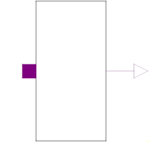 Partial Block Modelica.Electrical.Digital.Interfaces.SISO
SISO is a partial model for the connection pattern with single (scalar) digital input and single (scalar) digital output. Besides the connectors it provides a rectangle for the icon which can be filled in by the component which inherits the SISO model.
| Type | Name | Description |
|---|---|---|
input DigitalInput | x | Connector of Digital input signal |
output DigitalOutput | y | Connector of Digital output signal |
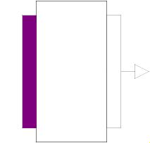
 Partial Block Modelica.Electrical.Digital.Interfaces.MISO
MISO is a partial model for the connection pattern with multiple (vector) digital input and single (scalar) digital output. Besides the connectors it provides a rectangle for the icon which can be filled in by the component which inherits the MISO model.
| Type | Name | Default | Description |
|---|---|---|---|
Integer | n | 2 | Number of inputs |
| Type | Name | Description |
|---|---|---|
input DigitalInput | x[n] | Connector of Digital input signal vector |
output DigitalOutput | y | Connector of Digital output signal |
 Partial Block Modelica.Electrical.Digital.Interfaces.MIMO
MIMO is a partial model for the connection pattern with multiple (vector) digital input and multiple (vector) digital output. Besides the connectors it provides a rectangle for the icon which can be filled in by the component which inherits the MISO model.
| Type | Name | Default | Description |
|---|---|---|---|
Integer | n | 1 | Number of inputs = Number of outputs |
| Type | Name | Description |
|---|---|---|
input DigitalInput | x[n] | Connector of Digital input signal vector |
output DigitalOutput | y[n] | Connector of Digital output signal vector |
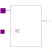 Partial Model Modelica.Electrical.Digital.Interfaces.MemoryBase
| Type | Name | Default | Description |
|---|---|---|---|
Time | tHL | 0 | High->Low delay |
Time | tLH | 0 | Low->High delay |
Strength | strength | S.'S_X01' | Output strength |
Integer | n_addr | 2 | Addr width |
Integer | n_data | 2 | Data width |
String | fileName | Modelica.Utilities.Files.loadResource("modelica://Modelica/Resources/Data/Electrical/Digital/Memory_Matrix.txt") | File where matrix for memory is stored |
| Type | Name | Description |
|---|---|---|
input DigitalInput | RE | Read enable |
input DigitalInput | addr[n_addr] | Address |
output DigitalOutput | dataOut[n_data] | Data output |