 Package Modelica.Electrical.Machines.Examples.ControlledDCDrives.Utilities
Utilities for controlled drives
Package Modelica.Electrical.Machines.Examples.ControlledDCDrives.Utilities
This package contains utilities for controlled drives
Extends from Modelica.Icons.UtilitiesPackage (Icon for utility packages).
| Name | Description |
|---|---|
Battery | Simple battery model |
DcdcInverter | DC-DC inverter |
DriveDataDCPM | Parameters of a controlled DC permanent magnet drive |
IdealDcDc | Ideal DC-DC inverter |
LimitedPI | Limited PI-controller with anti-windup and feed-forward |
PartialControlledDCPM | Partial controlled DC PM drive with H-bridge from battery |
SwitchingDcDc | Switching DC-DC inverter |
 Partial Model Modelica.Electrical.Machines.Examples.ControlledDCDrives.Utilities.PartialControlledDCPM
This is a partial model of a controlled DC PM drive.
Electrical power is taken from a battery (constant voltage with inner resistance) and fed to the motor via a DC-DC inverter. The level of detail of the DC-DC inverter may be chosen from ideal averaging or switching. The DC-DC inverter is commanded by the current controller. The current controller is parameterized according to the absolute optimum.
Further reading: Tutorial at the Modelica Conference 2017
Extends from Modelica.Icons.Example (Icon for runnable examples).
| Type | Name | Default | Description |
|---|---|---|---|
DriveDataDCPM | driveData |
 Record Modelica.Electrical.Machines.Examples.ControlledDCDrives.Utilities.DriveDataDCPM
Calculates controller parameters of a DC permanent magnet drive: Current controller according to absolute optimum, speed controller according to symmetric optimum.
Extends from Modelica.Icons.Record (Icon for records).
| Type | Name | Description |
|---|---|---|
parameter DcPermanentMagnetData | motorData | Motor data |
parameter Resistance | Ra | Armature resistance at nominal temperature |
parameter Time | Ta | Armature time constant |
parameter Power | PNominal | Nominal mechanical output |
parameter Torque | tauNominal | Nominal torque |
parameter ElectricalTorqueConstant | kPhi | Torque constant |
parameter AngularVelocity | w0 | No-load speed |
parameter Frequency | fS | Switching frequency |
parameter Voltage | VBat | DC no-load voltage |
parameter Time | Td | Dead time of inverter |
parameter Time | Tmf | Measurement filter time constant |
parameter Time | Tsigma | Sum of small time constants |
parameter Inertia | JL | Load inertia |
parameter Voltage | VaMax | Maximum Voltage |
parameter Current | IaMax | Maximum current |
parameter Torque | tauMax | Maximum torque |
parameter AngularVelocity | wMax | Maximum speed |
parameter AngularAcceleration | aMax | Maximum acceleration |
parameter Real | kpI | Proportional gain |
parameter Time | TiI | Integral time constant |
parameter Time | Tsub | Substitute time constant |
parameter Real | kpw | Proportional gain |
parameter Time | Tiw | Integral time constant |
parameter Time | Tfw | Filter time constant |
parameter Real | kpP | Proportional gain |
 Block Modelica.Electrical.Machines.Examples.ControlledDCDrives.Utilities.LimitedPI
Proportional - Integral - controller with optional feed-forward and limitation at the output.
The integral part can be switched off to obtain a limited P-controller.
The feed-forward gain can either be constant or given by the optional input kFF.
When the output is limited, the controller cannot bring the control error to zero and the integrator will not stop integrating. To avoid this WindUp - effect, an Anti-WindUp loop is implemented: The difference between unlimited and limited output is fed back to the integrator's input.
Extends from Modelica.Blocks.Interfaces.SISO (Single Input Single Output continuous control block).
| Type | Name | Default | Description |
|---|---|---|---|
Real | k | 1 | Gain |
Boolean | useI | true | PI else P |
Time | Ti | 1 | Integral time constant (T>0 required) |
Boolean | useFF | false | Use feed-forward? |
Boolean | useConstantKFF | true | Use constant feed-forward factor? |
Real | KFF | 1 | Feed-forward gain |
Boolean | constantLimits | true | Use constant limits? |
Boolean | symmetricLimits | true | Use symmetric limits? |
Real | yMax | inf | Upper limit of output |
Real | yMin | -yMax | Lower limit of output |
Init | initType | Modelica.Blocks.Types.Init.NoInit | Type of initialization (1: no init, 2: steady state, 3: initial state, 4: initial output) |
Real | x_start | 0 | Initial or guess value of state |
Real | y_start | 0 | Initial value of output |
| Type | Name | Description |
|---|---|---|
input RealInput | u | Connector of Real input signal |
output RealOutput | y | Connector of Real output signal |
input RealInput | u_m | Connector of measured signal |
input RealInput | feedForward | Connector of feed-forward signal |
input RealInput | kFF | Connector of feed-forward factor |
input RealInput | yMaxVar | Connector of yMax input signal |
input RealInput | yMinVar | Connector of yMin input signal |
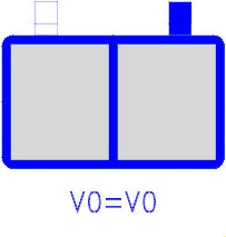 Model Modelica.Electrical.Machines.Examples.ControlledDCDrives.Utilities.Battery
This is a simple model of a DC-source resp. battery, consisting of a constant DC-voltage and an inner resistance.
| Type | Name | Default | Description |
|---|---|---|---|
Voltage | V0 | No-load voltage | |
Current | INominal | Nominal current | |
Resistance | Ri | 0.05 * V0 / INominal | Inner resistance |
| Type | Name | Description |
|---|---|---|
PositivePin | pin_p | |
NegativePin | pin_n |
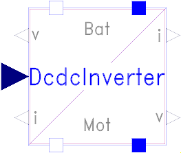 Model Modelica.Electrical.Machines.Examples.ControlledDCDrives.Utilities.DcdcInverter
This is a model of a DC-DC inverter. The level of detail of the DC-DC inverter may be chosen from ideal averaging or switching.
Reference voltage is limited to actual battery voltage.
Battery voltage and motor current are measured.
| Type | Name | Default | Description |
|---|---|---|---|
Boolean | useIdealInverter | true | Use ideal averaging inverter, otherwise switching inverter |
Frequency | fS | Switching frequency | |
Time | Td | 0.5 / fS | Dead time |
Time | Tmf | 2 / fS | Measurement filter time constant |
Voltage | VMax | Maximum Voltage | |
Time | Ti | 1e-6 | Time constant of integral power controller |
Resistance | RonT | 1e-5 | Transistor closed resistance |
Conductance | GoffT | 1e-5 | Transistor opened conductance |
Voltage | VkneeT | 0 | Transistor threshold voltage |
Resistance | RonD | 1e-5 | Diode closed resistance |
Conductance | GoffD | 1e-5 | Diode opened conductance |
Voltage | VkneeD | 0 | Diode threshold voltage |
| Type | Name | Description |
|---|---|---|
PositivePin | pin_pBat | |
NegativePin | pin_nBat | |
PositivePin | pin_pMot | |
NegativePin | pin_nMot | |
input RealInput | vRef | |
output RealOutput | vDC | |
output RealOutput | iDC | |
output RealOutput | vMot | |
output RealOutput | iMot |
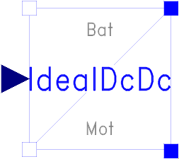 Model Modelica.Electrical.Machines.Examples.ControlledDCDrives.Utilities.IdealDcDc
This is a model of an ideal DC-DC inverter based on a power balance achieved by an integral controller.
| Type | Name | Default | Description |
|---|---|---|---|
Time | Td | Dead time | |
Time | Ti | 1e-6 | Time constant of integral power controller |
| Type | Name | Description |
|---|---|---|
NegativePin | pin_nBat | |
PositivePin | pin_pBat | |
NegativePin | pin_nMot | |
PositivePin | pin_pMot | |
input RealInput | vRef |
 Model Modelica.Electrical.Machines.Examples.ControlledDCDrives.Utilities.SwitchingDcDc
This is a model of a switching DC-DC inverter based on a H-bridge.
| Type | Name | Default | Description |
|---|---|---|---|
Frequency | fS | Switching frequency | |
Voltage | VMax | Maximum Voltage | |
Resistance | RonT | 1e-5 | Transistor closed resistance |
Conductance | GoffT | 1e-5 | Transistor opened conductance |
Voltage | VkneeT | 0 | Transistor threshold voltage |
Resistance | RonD | 1e-5 | Diode closed resistance |
Conductance | GoffD | 1e-5 | Diode opened conductance |
Voltage | VkneeD | 0 | Diode threshold voltage |
| Type | Name | Description |
|---|---|---|
NegativePin | pin_nBat | |
PositivePin | pin_pBat | |
PositivePin | pin_pMot | |
NegativePin | pin_nMot | |
input RealInput | vRef | |
input RealInput | vMax |