 Package Modelica.Electrical.Machines.Sensors
Sensors for machine modelling
Package Modelica.Electrical.Machines.SensorsThis package contains sensors that are useful when modelling machines.
Extends from Modelica.Icons.SensorsPackage (Icon for packages containing sensors).
| Name | Description |
|---|---|
CurrentQuasiRMSSensor | Length of space phasor -> RMS current |
ElectricalPowerSensor | Instantaneous power from space phasors |
HallSensor | Hall sensor |
MechanicalPowerSensor | Mechanical power = torque x speed |
RotorDisplacementAngle | Rotor lagging angle |
VoltageQuasiRMSSensor | Length of space phasor -> RMS voltage |
 Model Modelica.Electrical.Machines.Sensors.VoltageQuasiRMSSensor
Measured 3-phase instantaneous voltages are transformed to the corresponding space phasor; output is length of the space phasor divided by sqrt(2), thus giving in sinusoidal stationary state RMS voltage.
Extends from Modelica.Icons.RotationalSensor (Icon representing a round measurement device).
| Type | Name | Description |
|---|---|---|
output RealOutput | V | |
PositivePlug | plug_p | |
NegativePlug | plug_n |
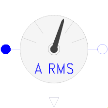 Model Modelica.Electrical.Machines.Sensors.CurrentQuasiRMSSensor
Measured 3-phase instantaneous currents are transformed to the corresponding space phasor; output is length of the space phasor divided by sqrt(2), thus giving in sinusoidal stationary state RMS current.
Extends from Modelica.Icons.RotationalSensor (Icon representing a round measurement device).
| Type | Name | Description |
|---|---|---|
output RealOutput | I | |
PositivePlug | plug_p | |
NegativePlug | plug_n |
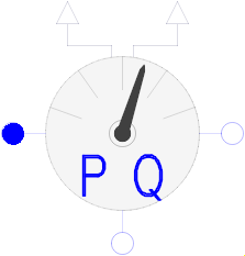 Model Modelica.Electrical.Machines.Sensors.ElectricalPowerSensor
3-phase instantaneous voltages (plug_p - plug_nv) and currents (plug_p - plug_ni) are transformed to the corresponding space phasors,
which are used to calculate power quantities:
Extends from Modelica.Icons.RotationalSensor (Icon representing a round measurement device).
| Type | Name | Description |
|---|---|---|
output RealOutput | P | |
output RealOutput | Q | |
PositivePlug | plug_p | |
NegativePlug | plug_ni | |
NegativePlug | plug_nv |
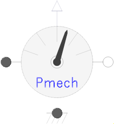 Model Modelica.Electrical.Machines.Sensors.MechanicalPowerSensor
Calculates (mechanical) power from torque times angular speed.
Extends from Modelica.Icons.RotationalSensor (Icon representing a round measurement device) and Modelica.Mechanics.Rotational.Interfaces.PartialTwoFlanges (Partial model for a component with two rotational 1-dim. shaft flanges).
| Type | Name | Default | Description |
|---|---|---|---|
Boolean | useSupport | false | Use support or fixed housing |
| Type | Name | Description |
|---|---|---|
Flange_a | flange_a | Flange of left shaft |
Flange_b | flange_b | Flange of right shaft |
output RealOutput | P | |
Flange_a | support | Support at which the reaction torque is acting |
 Model Modelica.Electrical.Machines.Sensors.RotorDisplacementAngle
Calculates rotor lagging angle by measuring the stator phase voltages, transforming them to the corresponding space phasor in stator-fixed coordinate system,
rotating the space phasor to the rotor-fixed coordinate system and calculating the angle of this space phasor.
The sensor's housing can be implicitly fixed (useSupport=false).
If the machine's stator also implicitly fixed (useSupport=false), the angle at the flange
is equal to the angle of the machine's rotor against the stator.
Otherwise, the sensor's support has to be connected to the machine's support.
| Type | Name | Default | Description |
|---|---|---|---|
Integer | m | 3 | Number of phases |
Integer | p | Number of pole pairs | |
Boolean | positiveRange | false | Use only positive output range, if true |
Real | threshold | 0 | Below threshold the voltage is considered as zero |
Boolean | useSupport | false | Use support or fixed housing |
| Type | Name | Description |
|---|---|---|
output RealOutput | rotorDisplacementAngle | |
PositivePlug | plug_p | |
NegativePlug | plug_n | |
Flange_a | flange | |
Flange_a | support | support at which the reaction torque is acting |
 Model Modelica.Electrical.Machines.Sensors.HallSensor
Simple model of a hall sensor, i.e. measuring the angle of the flange (w.r.t. the optional support), multiplying by the number of phases p to obtain the electrical angle, and adding a correction term i.e. the initial angle of the flange phi0.
Note that phi0 has to be set that way, that in shaft position phi0 the flux linkage of phase 1 is a maximum.
Extends from Modelica.Mechanics.Rotational.Interfaces.PartialElementaryOneFlangeAndSupport2 (Partial model for a component with one rotational 1-dim. shaft flange and a support used for textual modeling, i.e., for elementary models).
| Type | Name | Default | Description |
|---|---|---|---|
Boolean | useSupport | false | = true, if support flange enabled, otherwise implicitly grounded |
Integer | p | Number of pole pairs | |
Angle | phi0 | -pi / p | Initial mechanical angle |
| Type | Name | Description |
|---|---|---|
Flange_b | flange | Flange of shaft |
Support | support | Support/housing of component |
output RealOutput | y | "Electrical angle" |