 Package Modelica.Electrical.Machines.Utilities
Library with auxiliary models for testing
Package Modelica.Electrical.Machines.UtilitiesThis package contains utility components for testing examples.
Extends from Modelica.Icons.UtilitiesPackage (Icon for utility packages).
| Name | Description |
|---|---|
CurrentController | Current controller |
FromDQ | Transform rotor fixed space phasor to instantaneous stator quantities |
MultiTerminalBox | Terminal box Y/D-connection |
ParameterRecords … | Parameter records |
RampedRheostat | Rheostat with linearly decreasing resistance |
SwitchedRheostat | Rheostat which is shortened after a given time |
SwitchYD | Y-D-switch |
SynchronousMachineData | Computes machine parameter from usual datasheet |
TerminalBox | Terminal box Y/D-connection |
ToDQ | Transform instantaneous stator inputs to rotor fixed space phasor |
TransformerData | Calculates Impedances from nominal values |
VfController | Voltage-Frequency-Controller |
VoltageController | Voltage controller |
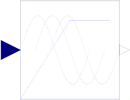 Block Modelica.Electrical.Machines.Utilities.VfController
Simple Voltage-Frequency-Controller.
Amplitude of voltage is linear dependent (VNominal/fNominal) on frequency (input signal "u"), but limited by VNominal (nominal RMS voltage per phase).
m sine-waves with amplitudes as described above are provided as output signal "y".
By setting parameter EconomyMode=true, Voltage rises quadratically with frequency which means flux,torque and loss reduction for fan and pump drives.
The sine-waves are intended to feed a m-phase SignalVoltage.
Phase shifts between sine-waves may be chosen by the user; default values are (k-1)/m*pi for k in 1:m.
Extends from Modelica.Blocks.Interfaces.SIMO (Single Input Multiple Output continuous control block).
| Type | Name | Default | Description |
|---|---|---|---|
final Integer | nout | m | Number of outputs |
Integer | m | 3 | Number of phases |
Angle | orientation[m] | -Modelica.Electrical.MultiPhase.Functions.symmetricOrientation(m) | Orientation of phases |
Voltage | VNominal | Nominal RMS voltage per phase | |
Frequency | fNominal | Nominal frequency | |
Angle | BasePhase | 0 | Common phase shift |
Boolean | EconomyMode | false | Economy mode: voltage quadratic dependent on frquency |
| Type | Name | Description |
|---|---|---|
input RealInput | u | Connector of Real input signal |
output RealOutput | y[nout] | Connector of Real output signals |
 Block Modelica.Electrical.Machines.Utilities.ToDQ
The multi phase input values u[m] are transformed to the corresponding space phasor which is rotated to the rotor fixed reference system,
using the provided mechanical rotor angle phi. The output are the resulting d and q components of the space phasor arranged in one vector y[2].
Extends from Modelica.Blocks.Interfaces.MIMO (Multiple Input Multiple Output continuous control block).
| Type | Name | Default | Description |
|---|---|---|---|
final Integer | nin | m | Number of inputs |
final Integer | nout | 2 | Number of outputs |
Integer | m | 3 | Number of phases |
Integer | p | Number of pole pairs |
| Type | Name | Description |
|---|---|---|
input RealInput | u[nin] | Connector of Real input signals |
output RealOutput | y[nout] | Connector of Real output signals |
input RealInput | phi |
 Block Modelica.Electrical.Machines.Utilities.FromDQ
The d and q components of a space phasor u[2] are rotated back to the stator fixed reference system,
using the provided mechanical rotor angle phi. The output are the instantaneous multi phase values y[m].
Extends from Modelica.Blocks.Interfaces.MIMO (Multiple Input Multiple Output continuous control block).
| Type | Name | Default | Description |
|---|---|---|---|
final Integer | nin | 2 | Number of inputs |
final Integer | nout | m | Number of outputs |
Integer | m | 3 | Number of phases |
Integer | p | Number of pole pairs |
| Type | Name | Description |
|---|---|---|
input RealInput | u[nin] | Connector of Real input signals |
output RealOutput | y[nout] | Connector of Real output signals |
input RealInput | phi |
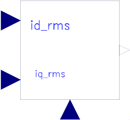 Model Modelica.Electrical.Machines.Utilities.CurrentController
Simple Current-Controller.
The desired rms values of d- and q-component of the space phasor current in rotor fixed coordinate system are given by inputs "id_rms" and "iq_rms". Using the given rotor position (input "phi"), the correct three-phase currents (output "y[3]") are calculated. They can be used to feed a current source which in turn feeds an induction machine.
Extends from Modelica.Blocks.Interfaces.MO (Multiple Output continuous control block).
| Type | Name | Default | Description |
|---|---|---|---|
Integer | m | 3 | Number of phases |
Integer | p | Number of pole pairs | |
final Integer | nout | m | Number of outputs |
| Type | Name | Description |
|---|---|---|
output RealOutput | y[nout] | Connector of Real output signals |
input RealInput | id_rms | |
input RealInput | iq_rms | |
input RealInput | phi |
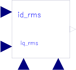 Model Modelica.Electrical.Machines.Utilities.VoltageController
Simple Voltage-Controller
The desired rms values of d- and q-component of the space phasor current in rotor fixed coordinate system are given by inputs "id_rms" and "iq_rms". Using the given rotor position (input "phi"), the actual threephase currents are measured and transformed to the d-q coordinate system. Two PI-controller determine the necessary d- and q- voltages, which are transformed back to threephase (output "y[3]"). They can be used to feed a voltage source which in turn feeds a permanent magnet synchronous machine.
Note: No care is taken for current or voltage limiting, as well as for field weakening.
Extends from Modelica.Blocks.Interfaces.MO (Multiple Output continuous control block).
| Type | Name | Default | Description |
|---|---|---|---|
Integer | p | Number of pole pairs | |
Frequency | fsNominal | Nominal frequency | |
Voltage | VsOpenCircuit | Open circuit RMS voltage per phase @ fsNominal | |
Resistance | Rs | Stator resistance per phase | |
Inductance | Ld | Inductance in d-axis | |
Inductance | Lq | Inductance in q-axis | |
Boolean | decoupling | false | Use decoupling network |
final MagneticFlux | psiM | sqrt(2) * VsOpenCircuit / (2 * pi * fsNominal) | |
final Integer | nout | m | Number of outputs |
| Type | Name | Description |
|---|---|---|
output RealOutput | y[nout] | Connector of Real output signals |
input RealInput | id_rms | |
input RealInput | iq_rms | |
input RealInput | phi | |
input RealInput | iActual[m] |
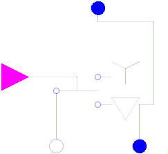 Model Modelica.Electrical.Machines.Utilities.SwitchYD
Simple Star-Delta-switch.
If control is false, plug_sp and plug_sn are star connected and plug_sp connected to the supply plug.
If control is true, plug_sp and plug_sn are delta connected and they are connected to the supply plug.
| Type | Name | Default | Description |
|---|---|---|---|
Integer | m | 3 | Number of phases |
| Type | Name | Description |
|---|---|---|
PositivePlug | plugSupply | To grid |
PositivePlug | plug_sp | To positive stator plug |
NegativePlug | plug_sn | To negative stator plug |
input BooleanInput | control[m] |
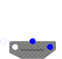
 Model Modelica.Electrical.Machines.Utilities.TerminalBox
TerminalBox: at the bottom connected to both machine plugs, connect at the top to the grid as usual,
choosing Y-connection (StarDelta=Y) or D-connection (StarDelta=D).
| Type | Name | Default | Description |
|---|---|---|---|
Integer | m | 3 | Number of phases |
String | terminalConnection | Choose Y=star/D=delta |
| Type | Name | Description |
|---|---|---|
PositivePlug | plug_sp | To positive stator plug |
NegativePlug | plug_sn | To negative stator plug |
PositivePlug | plugSupply | To grid |
NegativePin | starpoint |
 Model Modelica.Electrical.Machines.Utilities.MultiTerminalBox
TerminalBox: at the bottom connected to both machine plugs, connect at the top to the grid as usual,
choosing Y-connection (StarDelta=Y) or D-connection (StarDelta=D).
| Type | Name | Default | Description |
|---|---|---|---|
Integer | m | 3 | number of phases |
final Integer | mSystems | Modelica.Electrical.MultiPhase.Functions.numberOfSymmetricBaseSystems(m) | |
final Integer | mBasic | integer(m / mSystems) | |
String | terminalConnection | Choose Y=star/D=delta |
| Type | Name | Description |
|---|---|---|
PositivePlug | plug_sp | To positive stator plug |
NegativePlug | plug_sn | To negative stator plug |
PositivePlug | plugSupply | To grid |
NegativePlug | starpoint |
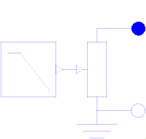
 Model Modelica.Electrical.Machines.Utilities.SwitchedRheostat
Switched rheostat, used for starting asynchronous induction motors with slipring rotor:
The external rotor resistance RStart is shortened at time tStart.
| Type | Name | Default | Description |
|---|---|---|---|
Integer | m | 3 | Number of phases |
Resistance | RStart | Starting resistance | |
Time | tStart | Duration of switching on the starting resistor |
| Type | Name | Description |
|---|---|---|
PositivePlug | plug_p | To positive rotor plug |
NegativePlug | plug_n | To negative rotor plug |
 Model Modelica.Electrical.Machines.Utilities.RampedRheostat
Ramped rheostat, used for starting asynchronous induction motors with slipring rotor:
The external rotor resistance RStart is reduced to zero,
starting at time tStart with a linear ramp tRamp.
| Type | Name | Default | Description |
|---|---|---|---|
Integer | m | 3 | Number of phases |
Resistance | RStart | Starting resistance | |
Time | tStart | Time instance of reducing the rheostat | |
Time | tRamp | Duration of ramp |
| Type | Name | Description |
|---|---|---|
PositivePlug | plug_p | To positive rotor plug |
NegativePlug | plug_n | To negative rotor plug |
 Record Modelica.Electrical.Machines.Utilities.SynchronousMachineData
The parameters of the synchronous machine model with electrical excitation (and damper) are calculated from parameters normally given in a technical description, according to the standard EN 60034-4:2008 Appendix C.
Extends from Modelica.Icons.Record (Icon for records).
| Type | Name | Description |
|---|---|---|
parameter ApparentPower | SNominal | Nominal apparent power |
parameter Voltage | VsNominal | Nominal stator voltage per phase |
parameter Current | IsNominal | Nominal stator current per phase |
parameter Impedance | ZReference | Reference impedance |
parameter Frequency | fsNominal | Nominal stator frequency |
parameter AngularVelocity | omega | Nominal angular frequency |
parameter Current | IeOpenCircuit | Open circuit excitation current @ nominal voltage and frequency |
parameter Real | effectiveStatorTurns | Effective number of stator turns |
parameter Real | turnsRatio | Stator current / excitation current |
parameter Real | x0 | Stator stray inductance per phase (approximately zero impedance) [pu] |
parameter Real | xd | Synchronous reactance per phase, d-axis [pu] |
parameter Real | xq | Synchronous reactance per phase, q-axis [pu] |
parameter Real | xdTransient | Transient reactance per phase, d-axis [pu] |
parameter Real | xdSubtransient | Subtransient reactance per phase, d-axis [pu] |
parameter Real | xqSubtransient | Subtransient reactance per phase, q-axis [pu] |
parameter Time | Ta | Armature time constant |
parameter Time | Td0Transient | Open circuit field time constant Td0' |
parameter Time | Td0Subtransient | Open circuit subtransient time constant Td0'', d-axis |
parameter Time | Tq0Subtransient | Open circuit subtransient time constant Tq0'', q-axis |
parameter Temperature | TsSpecification | Specification temperature of stator resistance |
parameter Temperature | TsRef | Reference temperature of stator resistance |
parameter LinearTemperatureCoefficient20 | alpha20s | Temperature coefficient of stator resistance at 20 degC |
parameter Temperature | TrSpecification | Specification temperature of (optional) damper cage |
parameter Temperature | TrRef | Reference temperature of damper resistances in d- and q-axis |
parameter LinearTemperatureCoefficient20 | alpha20r | Temperature coefficient of damper resistances in d- and q-axis |
parameter Temperature | TeSpecification | Specification excitation temperature |
parameter Temperature | TeRef | Reference temperature of excitation resistance |
parameter LinearTemperatureCoefficient20 | alpha20e | Temperature coefficient of excitation resistance |
parameter Real | xmd | Main field reactance per phase, d-axis [pu] |
parameter Real | xmq | Main field reactance per phase, q-axis [pu] |
parameter Real | xe | Excitation reactance [pu] |
parameter Real | xrd | Damper reactance per phase, d-axis [pu] |
parameter Real | xrq | Damper reactance per phase, d-axis [pu] |
parameter Real | rs | Stator resistance per phase at specification temperature [pu] |
parameter Real | rrd | Damper resistance per phase at specification temperature, d-axis [pu] |
parameter Real | rrq | Damper resistance per phase at specification temperature, q-axis [pu] |
parameter Real | re | Excitation resistance per phase at specification temperature [pu] |
parameter Resistance | Rs | Stator resistance per phase at TRef |
parameter Inductance | Lssigma | Stator stray inductance per phase |
parameter Inductance | Lmd | Main field inductance per phase in d-axis |
parameter Inductance | Lmq | Main field inductance per phase in q-axis |
parameter Inductance | Lrsigmad | Damper stray inductance in d-axis |
parameter Inductance | Lrsigmaq | Damper stray inductance in q-axis |
parameter Resistance | Rrd | Damper resistance in d-axis at TRef |
parameter Resistance | Rrq | Damper resistance in q-axis at TRef |
parameter Resistance | Re | Excitation resistance at TRef |
parameter Real | sigmae | Stray fraction of total excitation inductance |
The parameters of the transformer models are calculated from parameters normally given in a technical description.
Extends from Modelica.Icons.Record (Icon for records).
| Type | Name | Description |
|---|---|---|
parameter Frequency | f | Nominal frequency |
parameter Voltage | V1 | Primary nominal line-to-line voltage (RMS) |
parameter String | C1 | Choose primary connection |
parameter Voltage | V2 | Secondary open circuit line-to-line voltage (RMS) @ primary nominal voltage |
parameter String | C2 | Choose secondary connection |
parameter ApparentPower | SNominal | Nominal apparent power |
parameter Real | v_sc | Impedance voltage drop pu |
parameter Power | P_sc | Short-circuit (copper) losses |
parameter Real | n | Ratio primary voltage (line-to-line) / secondary voltage (line-to-line) |
parameter Voltage | V1ph | Primary phase voltage (RMS) |
parameter Current | I1ph | Primary phase current (RMS) |
parameter Voltage | V2ph | Secondary phase voltage (RMS) |
parameter Current | I2ph | Secondary phase current (RMS) |
parameter Impedance | Z1ph | Primary impedance per phase |
parameter Resistance | R1 | Warm primary resistance per phase |
parameter Inductance | L1sigma | Primary stray inductance per phase |
parameter Impedance | Z2ph | Secondary impedance per phase |
parameter Resistance | R2 | Warm secondary resistance per phase |
parameter Inductance | L2sigma | Secondary stray inductance per phase |