 Package Modelica.Mechanics.MultiBody.Forces
Components that exert forces and/or torques between frames
Package Modelica.Mechanics.MultiBody.Forces
This package contains components that exert forces and torques between two frame connectors, e.g., between two parts.
| Model | Description |
|---|---|
| WorldForce | External force acting at the frame to which this component
is connected and defined by 3 input signals,
that are interpreted as one vector resolved in frame world, frame_b or frame_resolve. |
| WorldTorque | External torque acting at the frame to which this component
is connected and defined by 3 input signals,
that are interpreted as one vector resolved in frame world, frame_b or frame_resolve. |
| WorldForceAndTorque | External force and external torque acting at the frame
to which this component
is connected and defined by 3+3 input signals,
that are interpreted as a force and as a torque vector
resolved in frame world, frame_b or frame_resolve.
|
| Force | Force acting between two frames defined by 3 input signals
resolved in frame world, frame_a, frame_b or in frame_resolve. |
| Torque | Torque acting between two frames defined by 3 input signals
resolved in frame world, frame_a, frame_b or in frame_resolve. |
| ForceAndTorque | Force and torque acting between two frames defined by 3+3 input signals
resolved in frame world, frame_a, frame_b or in frame_resolve. |
| LineForceWithMass | General line force component with an optional point mass
on the connection line. The force law can be defined by a
component of Modelica.Mechanics.Translational |
| LineForceWithTwoMasses | General line force component with two optional point masses
on the connection line. The force law can be defined by a
component of Modelica.Mechanics.Translational |
| Spring | Linear translational spring with optional mass |
| Damper | Linear (velocity dependent) damper |
| SpringDamperParallel | Linear spring and damper in parallel connection |
| SpringDamperSeries | Linear spring and damper in series connection |
Extends from Modelica.Icons.SourcesPackage (Icon for packages containing sources).
| Name | Description |
|---|---|
Damper | Linear (velocity dependent) damper |
Force | Force acting between two frames, defined by 3 input signals and resolved in frame world, frame_a, frame_b or frame_resolve |
ForceAndTorque | Force and torque acting between two frames, defined by 3+3 input signals and resolved in frame world, frame_a, frame_b or frame_resolve |
Internal … | Internal package, should not be used by user |
LineForceWithMass | General line force component with an optional point mass on the connection line |
LineForceWithTwoMasses | General line force component with two optional point masses on the connection line |
Spring | Linear translational spring with optional mass |
SpringDamperParallel | Linear spring and linear damper in parallel |
SpringDamperSeries | Linear spring and linear damper in series connection |
Torque | Torque acting between two frames, defined by 3 input signals and resolved in frame world, frame_a, frame_b or frame_resolve |
WorldForce | External force acting at frame_b, defined by 3 input signals and resolved in frame world, frame_b or frame_resolve |
WorldForceAndTorque | External force and torque acting at frame_b, defined by 3+3 input signals and resolved in frame world, frame_b or in frame_resolve |
WorldTorque | External torque acting at frame_b, defined by 3 input signals and resolved in frame world, frame_b or frame_resolve |
 Model Modelica.Mechanics.MultiBody.Forces.WorldForce
The 3 signals of the force connector are interpreted as the x-, y- and z-coordinates of a force acting at the frame connector to which frame_b of this component is attached. Via parameter resolveInFrame it is defined, in which frame these coordinates shall be resolved:
| Types.ResolveInFrameB. | Meaning |
|---|---|
| world | Resolve input force in world frame (= default) |
| frame_b | Resolve input force in frame_b |
| frame_resolve | Resolve input force in frame_resolve (frame_resolve must be connected) |
If resolveInFrame = Types.ResolveInFrameB.frame_resolve, the force coordinates are with respect to the frame, that is connected to frame_resolve.
If force={100,0,0}, and for all parameters the default setting is used, then the interpretation is that a force of 100 N is acting along the positive x-axis of frame_b.
Note, the cut-torque in frame_b (frame_b.t) is always set to zero. Conceptually, a force and torque acts on the world frame in such a way that the force and torque balance between world.frame_b and frame_b is fulfilled. For efficiency reasons, this reaction torque is, however, not computed.
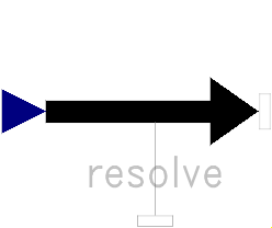
This force component is by default visualized as an arrow acting at the connector to which it is connected. The diameter and color of the arrow can be defined via variables diameter and color. The arrow points in the direction defined by the force signal. The length of the arrow is proportional to the length of the force vector using parameter N_to_m as scaling factor. For example, if N_to_m = 100 N/m, then a force of 350 N is displayed as an arrow of length 3.5 m.
An example how to use this model is given in the following figure:
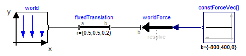
This leads to the following animation
Extends from Modelica.Mechanics.MultiBody.Interfaces.PartialOneFrame_b (Base model for components providing one frame_b connector + outer world + assert to guarantee that the component is connected).
| Type | Name | Default | Description |
|---|---|---|---|
Boolean | animation | true | = true, if animation shall be enabled |
ResolveInFrameB | resolveInFrame | Modelica.Mechanics.MultiBody.Types.ResolveInFrameB.world | Frame in which input force is resolved (1: world, 2: frame_b, 3: frame_resolve) |
Real | N_to_m | world.defaultN_to_m | Force arrow scaling (length = force/N_to_m) |
| Type | Name | Default | Description |
|---|---|---|---|
Diameter | diameter | world.defaultArrowDiameter | Diameter of force arrow |
Color | color[3] | Modelica.Mechanics.MultiBody.Types.Defaults.ForceColor | Color of arrow |
SpecularCoefficient | specularCoefficient | world.defaultSpecularCoefficient | Reflection of ambient light (= 0: light is completely absorbed) |
| Type | Name | Description |
|---|---|---|
Frame_b | frame_b | Coordinate system fixed to the component with one cut-force and cut-torque |
Frame_resolve | frame_resolve | The input signals are optionally resolved in this frame |
input RealInput | force[3] | x-, y-, z-coordinates of force resolved in frame defined by resolveInFrame |
 Model Modelica.Mechanics.MultiBody.Forces.WorldTorque
The 3 signals of the torque connector are interpreted as the x-, y- and z-coordinates of a torque acting at the frame connector to which frame_b of this component is attached. Via parameter resolveInFrame it is defined, in which frame these coordinates shall be resolved:
| Types.ResolveInFrameB. | Meaning |
|---|---|
| world | Resolve input torque in world frame (= default) |
| frame_b | Resolve input torque in frame_b |
| frame_resolve | Resolve input torque in frame_resolve (frame_resolve must be connected) |
If resolveInFrame = Types.ResolveInFrameB.frame_resolve, the torque coordinates are with respect to the frame, that is connected to frame_resolve.
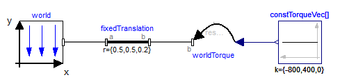
If torque={100,0,0}, and for all parameters the default setting is used, then the interpretation is that a torque of 100 N is acting along the positive x-axis of frame_b.
Note, the cut-force in frame_b (frame_b.f) is always set to zero. Conceptually, a force and torque acts on the world frame in such a way that the force and torque balance between world.frame_b and frame_b is fulfilled. For efficiency reasons, this reaction torque is, however, not computed.
This torque component is by default visualized as a double arrow acting at the connector to which it is connected. The diameter and color of the arrow can be defined via variables diameter and color. The double arrow points in the direction defined by the torque vector. The length of the double arrow is proportional to the length of the torque vector using parameter Nm_to_m as scaling factor. For example, if Nm_to_m = 100 Nm/m, then a torque of 350 Nm is displayed as an arrow of length 3.5 m.
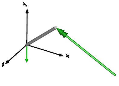
An example how to use this model is given in the following figure:
This leads to the following animation
Extends from Modelica.Mechanics.MultiBody.Interfaces.PartialOneFrame_b (Base model for components providing one frame_b connector + outer world + assert to guarantee that the component is connected).
| Type | Name | Default | Description |
|---|---|---|---|
Boolean | animation | true | = true, if animation shall be enabled |
ResolveInFrameB | resolveInFrame | Modelica.Mechanics.MultiBody.Types.ResolveInFrameB.world | Frame in which input torque is resolved (1: world, 2: frame_b, 3: frame_resolve) |
Real | Nm_to_m | world.defaultNm_to_m | Torque arrow scaling (length = torque/Nm_to_m) |
| Type | Name | Default | Description |
|---|---|---|---|
Diameter | diameter | world.defaultArrowDiameter | Diameter of torque arrow |
Color | color[3] | Modelica.Mechanics.MultiBody.Types.Defaults.TorqueColor | Color of arrow |
SpecularCoefficient | specularCoefficient | world.defaultSpecularCoefficient | Reflection of ambient light (= 0: light is completely absorbed) |
| Type | Name | Description |
|---|---|---|
Frame_b | frame_b | Coordinate system fixed to the component with one cut-force and cut-torque |
Frame_resolve | frame_resolve | The input signals are optionally resolved in this frame |
input RealInput | torque[3] | x-, y-, z-coordinates of torque resolved in frame defined by resolveInFrame |
 Model Modelica.Mechanics.MultiBody.Forces.WorldForceAndTorque
The 3 signals of the force and torque connector are interpreted as the x-, y- and z-coordinates of a force and torque acting at the frame connector to which frame_b of this component is attached. Via parameter resolveInFrame it is defined, in which frame these coordinates shall be resolved:
| Types.ResolveInFrameB. | Meaning |
|---|---|
| world | Resolve input force and torque in world frame (= default) |
| frame_b | Resolve input force and torque in frame_b |
| frame_resolve | Resolve input force and torque in frame_resolve (frame_resolve must be connected) |
If resolveInFrame = Types.ResolveInFrameB.frame_resolve, the force and torque coordinates are with respect to the frame, that is connected to frame_resolve.
If force={100,0,0}, and for all parameters the default setting is used, then the interpretation is that a force of 100 N is acting along the positive x-axis of frame_b.
Conceptually, a force and torque acts on the world frame in such a way that the force and torque balance between world.frame_b and frame_b is fulfilled. For efficiency reasons, this reaction torque is, however, not computed.
The force and torque are by default visualized as an arrow (force) and as a double arrow (torque) acting at the connector to which they are connected. The diameters and colors of the arrows can be defined via variables forceDiameter, torqueDiameter, forceColor and torqueColor. The arrows point in the directions defined by the force and torque vectors. The lengths of the arrows are proportional to the length of the force and torque vectors, respectively, using parameters N_to_m and Nm_to_m as scaling factors. For example, if N_to_m = 100 N/m, then a force of 350 N is displayed as an arrow of length 3.5 m.
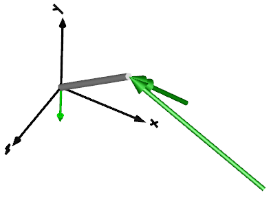
An example how to use this model is given in the following figure:
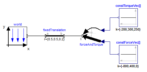
This leads to the following animation
Extends from Modelica.Mechanics.MultiBody.Interfaces.PartialOneFrame_b (Base model for components providing one frame_b connector + outer world + assert to guarantee that the component is connected).
| Type | Name | Default | Description |
|---|---|---|---|
Boolean | animation | true | = true, if animation shall be enabled |
ResolveInFrameB | resolveInFrame | Modelica.Mechanics.MultiBody.Types.ResolveInFrameB.world | Frame in which input force and torque are resolved (1: world, 2: frame_b, 3: frame_resolve) |
Real | N_to_m | world.defaultN_to_m | Force arrow scaling (length = force/N_to_m) |
Real | Nm_to_m | world.defaultNm_to_m | Torque arrow scaling (length = torque/Nm_to_m) |
| Type | Name | Default | Description |
|---|---|---|---|
Diameter | forceDiameter | world.defaultArrowDiameter | Diameter of force arrow |
Diameter | torqueDiameter | forceDiameter | Diameter of torque arrow |
Color | forceColor[3] | Modelica.Mechanics.MultiBody.Types.Defaults.ForceColor | Color of force arrow |
Color | torqueColor[3] | Modelica.Mechanics.MultiBody.Types.Defaults.TorqueColor | Color of torque arrow |
SpecularCoefficient | specularCoefficient | world.defaultSpecularCoefficient | Reflection of ambient light (= 0: light is completely absorbed) |
| Type | Name | Description |
|---|---|---|
Frame_b | frame_b | Coordinate system fixed to the component with one cut-force and cut-torque |
Frame_resolve | frame_resolve | The input signals are optionally resolved in this frame |
input RealInput | force[3] | x-, y-, z-coordinates of force resolved in frame defined by resolveInFrame |
input RealInput | torque[3] | x-, y-, z-coordinates of torque resolved in frame defined by resolveInFrame |
 Model Modelica.Mechanics.MultiBody.Forces.Force
The 3 signals of the force connector are interpreted as the x-, y- and z-coordinates of a force acting at the frame connector to which frame_b of this component is attached. Via parameter resolveInFrame it is defined, in which frame these coordinates shall be resolved:
| Types.ResolveInFrameAB. | Meaning |
|---|---|
| world | Resolve input force in world frame |
| frame_a | Resolve input force in frame_a |
| frame_b | Resolve input force in frame_b (= default) |
| frame_resolve | Resolve input force in frame_resolve (frame_resolve must be connected) |
If resolveInFrame = ResolveInFrameAB.frame_resolve, the force coordinates are with respect to the frame, that is connected to frame_resolve.
If force={100,0,0}, and for all parameters the default setting is used, then the interpretation is that a force of 100 N is acting along the positive x-axis of frame_b.
Note, the cut-torque in frame_b (frame_b.t) is always set to zero. Additionally, a force and torque acts on frame_a in such a way that the force and torque balance between frame_a and frame_b is fulfilled.
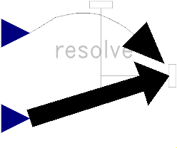
An example how to use this model is given in the following figure:
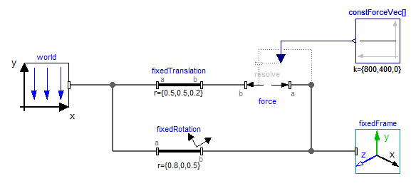
This leads to the following animation (the yellow cylinder characterizes the line between frame_a and frame_b of the Force component, i.e., the force acts with negative sign also on the opposite side of this cylinder, but for clarity this is not shown in the animation):
Extends from Modelica.Mechanics.MultiBody.Interfaces.PartialTwoFrames (Base model for components providing two frame connectors + outer world + assert to guarantee that the component is connected).
| Type | Name | Default | Description |
|---|---|---|---|
Boolean | animation | true | = true, if animation shall be enabled |
ResolveInFrameAB | resolveInFrame | Modelica.Mechanics.MultiBody.Types.ResolveInFrameAB.frame_b | Frame in which input force is resolved (1: world, 2: frame_a, 3: frame_b, 4: frame_resolve) |
Real | N_to_m | world.defaultN_to_m | Force arrow scaling (length = force/N_to_m) |
| Type | Name | Default | Description |
|---|---|---|---|
Diameter | forceDiameter | world.defaultArrowDiameter | Diameter of force arrow |
Diameter | connectionLineDiameter | forceDiameter | Diameter of line connecting frame_a and frame_b |
Color | forceColor[3] | Modelica.Mechanics.MultiBody.Types.Defaults.ForceColor | Color of force arrow |
Color | connectionLineColor[3] | Modelica.Mechanics.MultiBody.Types.Defaults.SensorColor | Color of line connecting frame_a and frame_b |
SpecularCoefficient | specularCoefficient | world.defaultSpecularCoefficient | Reflection of ambient light (= 0: light is completely absorbed) |
| Type | Name | Description |
|---|---|---|
Frame_a | frame_a | Coordinate system a fixed to the component with one cut-force and cut-torque |
Frame_b | frame_b | Coordinate system b fixed to the component with one cut-force and cut-torque |
Frame_resolve | frame_resolve | The input signals are optionally resolved in this frame |
input RealInput | force[3] | x-, y-, z-coordinates of force resolved in frame defined by resolveInFrame |
 Model Modelica.Mechanics.MultiBody.Forces.Torque
The 3 signals of the torque connector are interpreted as the x-, y- and z-coordinates of a torque acting at the frame connector to which frame_b of this component is attached. Via parameter resolveInFrame it is defined, in which frame these coordinates shall be resolved:
| Types.ResolveInFrameAB. | Meaning |
|---|---|
| world | Resolve input torque in world frame |
| frame_a | Resolve input torque in frame_a |
| frame_b | Resolve input torque in frame_b (= default) |
| frame_resolve | Resolve input torque in frame_resolve (frame_resolve must be connected) |
If resolveInFrame = ResolveInFrameAB.frame_resolve, the torque coordinates are with respect to the frame, that is connected to frame_resolve.
If torque={100,0,0}, and for all parameters the default setting is used, then the interpretation is that a torque of 100 N.m is acting along the positive x-axis of frame_b.
Note, the cut-forces in frame_a and frame_b (frame_a.f, frame_b.f) are always set to zero and the cut-torque at frame_a (frame_a.t) is the same as the cut-torque at frame_b (frame_b.t) but with opposite sign.
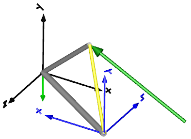
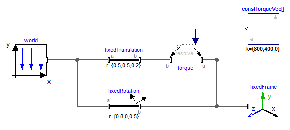
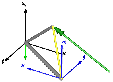
An example how to use this model is given in the following figure:
This leads to the following animation (the yellow cylinder characterizes the line between frame_a and frame_b of the Torque component, i.e., the torque acts with negative sign also on the opposite side of this cylinder, but for clarity this is not shown in the animation):
Extends from Modelica.Mechanics.MultiBody.Interfaces.PartialTwoFrames (Base model for components providing two frame connectors + outer world + assert to guarantee that the component is connected).
| Type | Name | Default | Description |
|---|---|---|---|
Boolean | animation | true | = true, if animation shall be enabled |
ResolveInFrameAB | resolveInFrame | Modelica.Mechanics.MultiBody.Types.ResolveInFrameAB.frame_b | Frame in which input force is resolved (1: world, 2: frame_a, 3: frame_b, 4: frame_resolve) |
Real | Nm_to_m | world.defaultNm_to_m | Torque arrow scaling (length = torque/Nm_to_m) |
| Type | Name | Default | Description |
|---|---|---|---|
Diameter | torqueDiameter | world.defaultArrowDiameter | Diameter of torque arrow |
Diameter | connectionLineDiameter | torqueDiameter | Diameter of line connecting frame_a and frame_b |
Color | torqueColor[3] | Modelica.Mechanics.MultiBody.Types.Defaults.TorqueColor | Color of torque arrow |
Color | connectionLineColor[3] | Modelica.Mechanics.MultiBody.Types.Defaults.SensorColor | Color of line connecting frame_a and frame_b |
SpecularCoefficient | specularCoefficient | world.defaultSpecularCoefficient | Reflection of ambient light (= 0: light is completely absorbed) |
| Type | Name | Description |
|---|---|---|
Frame_a | frame_a | Coordinate system a fixed to the component with one cut-force and cut-torque |
Frame_b | frame_b | Coordinate system b fixed to the component with one cut-force and cut-torque |
Frame_resolve | frame_resolve | The input signals are optionally resolved in this frame |
input RealInput | torque[3] | x-, y-, z-coordinates of torque resolved in frame defined by resolveInFrame |
 Model Modelica.Mechanics.MultiBody.Forces.ForceAndTorque
The 3 signals of the force connector and the 3 signals of the torque connector are interpreted as the x-, y- and z-coordinates of a force and of a torque acting at the frame connector to which frame_b of this component is attached. Via parameter resolveInFrame it is defined, in which frame these coordinates shall be resolved:
| Types.ResolveInFrameAB. | Meaning |
|---|---|
| world | Resolve input force/torque in world frame |
| frame_a | Resolve input force/torque in frame_a |
| frame_b | Resolve input force/torque in frame_b (= default) |
| frame_resolve | Resolve input force/torque in frame_resolve (frame_resolve must be connected) |
If resolveInFrame = ResolveInFrameAB.frame_resolve, the force and torque coordinates are with respect to the frame, that is connected to frame_resolve.
If force={100,0,0}, and for all parameters the default setting is used, then the interpretation is that a force of 100 N is acting along the positive x-axis of frame_b.
Note, a force and torque acts on frame_a in such a way that the force and torque balance between frame_a and frame_b is fulfilled.
An example how to use this model is given in the following figure:
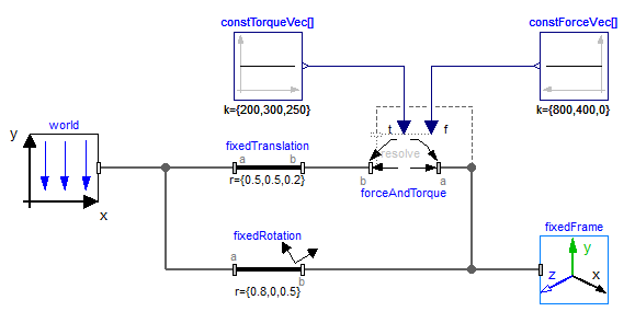
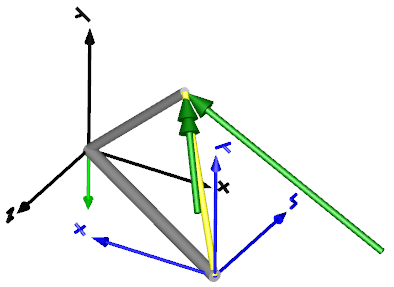
This leads to the following animation (the yellow cylinder characterizes the line between frame_a and frame_b of the ForceAndTorque component, i.e., the force and torque acts with negative sign also on the opposite side of this cylinder, but for clarity this is not shown in the animation):
Extends from Modelica.Mechanics.MultiBody.Interfaces.PartialTwoFrames (Base model for components providing two frame connectors + outer world + assert to guarantee that the component is connected).
| Type | Name | Default | Description |
|---|---|---|---|
Boolean | animation | true | = true, if animation shall be enabled |
ResolveInFrameAB | resolveInFrame | Modelica.Mechanics.MultiBody.Types.ResolveInFrameAB.frame_b | Frame in which input force and torque are resolved (1: world, 2: frame_a, 3: frame_b, 4: frame_resolve) |
Real | N_to_m | world.defaultN_to_m | Force arrow scaling (length = force/N_to_m) |
Real | Nm_to_m | world.defaultNm_to_m | Torque arrow scaling (length = torque/Nm_to_m) |
| Type | Name | Default | Description |
|---|---|---|---|
Diameter | forceDiameter | world.defaultArrowDiameter | Diameter of force arrow |
Diameter | torqueDiameter | forceDiameter | Diameter of torque arrow |
Diameter | connectionLineDiameter | forceDiameter | Diameter of line connecting frame_a and frame_b |
Color | forceColor[3] | Modelica.Mechanics.MultiBody.Types.Defaults.ForceColor | Color of force arrow |
Color | torqueColor[3] | Modelica.Mechanics.MultiBody.Types.Defaults.TorqueColor | Color of torque arrow |
Color | connectionLineColor[3] | Modelica.Mechanics.MultiBody.Types.Defaults.SensorColor | Color of line connecting frame_a and frame_b |
SpecularCoefficient | specularCoefficient | world.defaultSpecularCoefficient | Reflection of ambient light (= 0: light is completely absorbed) |
| Type | Name | Description |
|---|---|---|
Frame_a | frame_a | Coordinate system a fixed to the component with one cut-force and cut-torque |
Frame_b | frame_b | Coordinate system b fixed to the component with one cut-force and cut-torque |
input RealInput | force[3] | x-, y-, z-coordinates of force resolved in frame defined by resolveInFrame |
input RealInput | torque[3] | x-, y-, z-coordinates of torque resolved in frame defined by resolveInFrame |
Frame_resolve | frame_resolve | The input signals are optionally resolved in this frame |
 Model Modelica.Mechanics.MultiBody.Forces.LineForceWithMass
This component is used to exert a line force between the origin of frame_a and the origin of frame_b by attaching components of the 1-dimensional translational mechanical library of Modelica (Modelica.Mechanics.Translational) between the two flange connectors flange_a and flange_b. Optionally, there is a point mass on the line connecting the origin of frame_a and the origin of frame_b. This point mass approximates the mass of the force element. The distance of the point mass from frame_a as a fraction of the distance between frame_a and frame_b is defined via parameter lengthFraction (default is 0.5, i.e., the point mass is in the middle of the line).
In the translational library there is the implicit assumption that forces of components that have only one flange connector act with opposite sign on the bearings of the component. This assumption is also used in the LineForceWithMass component: If a connection is present to only one of the flange connectors, then the force in this flange connector acts implicitly with opposite sign also in the other flange connector.
Extends from Modelica.Mechanics.MultiBody.Interfaces.LineForceBase (Base model for line force elements).
| Type | Name | Default | Description |
|---|---|---|---|
Distance | s_small | 1e-10 | Prevent zero-division if distance between frame_a and frame_b is zero |
Boolean | fixedRotationAtFrame_a | false | =true, if rotation frame_a.R is fixed (to directly connect line forces) |
Boolean | fixedRotationAtFrame_b | false | =true, if rotation frame_b.R is fixed (to directly connect line forces) |
Boolean | animateLine | true | = true, if a line shape between frame_a and frame_b shall be visualized |
Boolean | animateMass | true | = true, if point mass shall be visualized as sphere provided m > 0 |
Mass | m | 0 | Mass of point mass on the connection line between the origin of frame_a and the origin of frame_b |
Real | lengthFraction | 0.5 | Location of point mass with respect to frame_a as a fraction of the distance from frame_a to frame_b |
ShapeType | lineShapeType | "cylinder" | Type of shape visualizing the line from frame_a to frame_b |
ShapeExtra | lineShapeExtra | 0 | Extra parameter for shape |
| Type | Name | Default | Description |
|---|---|---|---|
SpecularCoefficient | specularCoefficient | world.defaultSpecularCoefficient | Reflection of ambient light (= 0: light is completely absorbed) |
Length | lineShapeWidth | world.defaultArrowDiameter | Width of shape |
Length | lineShapeHeight | lineShapeWidth | Height of shape |
Color | lineShapeColor[3] | Modelica.Mechanics.MultiBody.Types.Defaults.SensorColor | Color of line shape |
Real | massDiameter | world.defaultBodyDiameter | Diameter of point mass sphere |
Color | massColor[3] | Modelica.Mechanics.MultiBody.Types.Defaults.BodyColor | Color of point mass |
| Type | Name | Description |
|---|---|---|
Frame_a | frame_a | Coordinate system a fixed to the component with one cut-force and cut-torque |
Frame_b | frame_b | Coordinate system b fixed to the component with one cut-force and cut-torque |
Flange_a | flange_b | 1-dim. translational flange (connect force of Translational library between flange_a and flange_b) |
Flange_b | flange_a | 1-dim. translational flange (connect force of Translational library between flange_a and flange_b) |
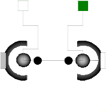 Model Modelica.Mechanics.MultiBody.Forces.LineForceWithTwoMasses
This component is used to exert a line force between the origin of frame_a and the origin of frame_b by attaching components of the 1-dimensional translational mechanical library of Modelica (Modelica.Mechanics.Translational) between the two flange connectors flange_a and flange_b. Optionally, there are two point masses on the line connecting the origin of frame_a and the origin of frame_b. These point masses approximate the masses of the force element. The locations of the two point masses are defined by their (fixed) distances of L_a relative to frame_a and of L_b relative to frame_b, respectively.
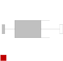
In example MultiBody.Examples.Elementary.LineForceWithTwoMasses the usage of this line force element is shown and is compared with an alternative implementation using a MultiBody.Joints.Assemblies.JointUPS component. The composition diagram of this example is displayed in the figure below.
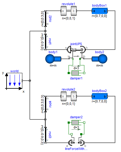
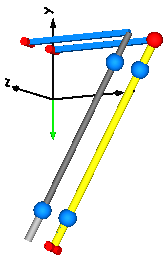
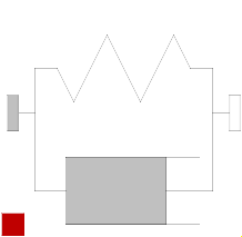
The animation view at time = 0 is shown in the next figure. The system on the left side in the front is the animation with the LineForceWithTwoMasses component whereas the system on the right side in the back is the animation with the JointUPS component. Both implementations yield the same result. However, the implementation with the LineForceWithTwoMasses component is simpler.
In the translational library there is the implicit assumption that forces of components that have only one flange connector act with opposite sign on the bearings of the component. This assumption is also used in the LineForceWithTwoMasses component: If a connection is present to only one of the flange connectors, then the force in this flange connector acts implicitly with opposite sign also in the other flange connector.
Extends from Modelica.Mechanics.MultiBody.Interfaces.LineForceBase (Base model for line force elements).
| Type | Name | Default | Description |
|---|---|---|---|
Distance | s_small | 1e-10 | Prevent zero-division if distance between frame_a and frame_b is zero |
Boolean | fixedRotationAtFrame_a | false | =true, if rotation frame_a.R is fixed (to directly connect line forces) |
Boolean | fixedRotationAtFrame_b | false | =true, if rotation frame_b.R is fixed (to directly connect line forces) |
Boolean | animate | true | = true, if animation shall be enabled |
Boolean | animateMasses | true | = true, if point masses shall be visualized provided animate=true and m_a, m_b > 0 |
Mass | m_a | 0 | Mass of point mass a on the connection line between the origin of frame_a and the origin of frame_b |
Mass | m_b | 0 | Mass of point mass b on the connection line between the origin of frame_a and the origin of frame_b |
Position | L_a | 0 | Distance between point mass a and frame_a (positive, if in direction of frame_b) |
Position | L_b | L_a | Distance between point mass b and frame_b (positive, if in direction of frame_a) |
Length | cylinderLength_a | 2 * L_a | Length of cylinder at frame_a |
Length | cylinderLength_b | 2 * L_b | Length of cylinder at frame_b |
| Type | Name | Default | Description |
|---|---|---|---|
SpecularCoefficient | specularCoefficient | world.defaultSpecularCoefficient | Reflection of ambient light (= 0: light is completely absorbed) |
Diameter | cylinderDiameter_a | world.defaultForceWidth | Diameter of cylinder at frame_a |
Color | color_a[3] | {155, 155, 155} | Color of cylinder at frame_a |
Real | diameterFraction | 0.8 | Diameter of cylinder at frame_b with respect to diameter of cylinder at frame_a |
Color | color_b[3] | {100, 100, 100} | Color of cylinder at frame_b |
Real | massDiameterFaction | 1.7 | Diameter of point mass spheres with respect to cylinderDiameter_a |
Color | massColor[3] | Modelica.Mechanics.MultiBody.Types.Defaults.BodyColor | Color of point masses |
| Type | Name | Description |
|---|---|---|
Frame_a | frame_a | Coordinate system a fixed to the component with one cut-force and cut-torque |
Frame_b | frame_b | Coordinate system b fixed to the component with one cut-force and cut-torque |
Flange_a | flange_b | 1-dim. translational flange (connect force of Translational library between flange_a and flange_b) |
Flange_b | flange_a | 1-dim. translational flange (connect force of Translational library between flange_a and flange_b) |
 Model Modelica.Mechanics.MultiBody.Forces.Spring
Linear spring acting as line force between frame_a and frame_b. A force f is exerted on the origin of frame_b and with opposite sign on the origin of frame_a along the line from the origin of frame_a to the origin of frame_b according to the equation:
f = c*(s - s_unstretched);
where "c" and "s_unstretched" are parameters and "s" is the distance between the origin of frame_a and the origin of frame_b.
Optionally, the mass of the spring is taken into account by a point mass located on the line between frame_a and frame_b (default: middle of the line). If the spring mass is zero, the additional equations to handle the mass are removed.
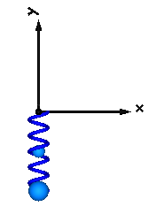
In the following figure a typical animation of the spring is shown. The blue sphere in the middle of the spring characterizes the location of the point mass.
Extends from Modelica.Mechanics.MultiBody.Interfaces.PartialTwoFrames (Base model for components providing two frame connectors + outer world + assert to guarantee that the component is connected).
| Type | Name | Default | Description |
|---|---|---|---|
Boolean | animation | true | = true, if animation shall be enabled |
Boolean | showMass | true | = true, if point mass shall be visualized as sphere if animation=true and m>0 |
TranslationalSpringConstant | c | Spring constant | |
Length | s_unstretched | 0 | Unstretched spring length |
Mass | m | 0 | Spring mass located on the connection line between the origin of frame_a and the origin of frame_b |
Real | lengthFraction | 0.5 | Location of spring mass with respect to frame_a as a fraction of the distance from frame_a to frame_b (=0: at frame_a; =1: at frame_b) |
Integer | numberOfWindings | 5 | Number of spring windings |
Distance | s_small | 1e-10 | Prevent zero-division if distance between frame_a and frame_b is zero |
Boolean | fixedRotationAtFrame_a | false | =true, if rotation frame_a.R is fixed (to directly connect line forces) |
Boolean | fixedRotationAtFrame_b | false | =true, if rotation frame_b.R is fixed (to directly connect line forces) |
| Type | Name | Default | Description |
|---|---|---|---|
Distance | width | world.defaultForceWidth | Width of spring |
Distance | coilWidth | 0.1 * width | Width of spring coil |
Color | color[3] | Modelica.Mechanics.MultiBody.Types.Defaults.SpringColor | Color of spring |
SpecularCoefficient | specularCoefficient | world.defaultSpecularCoefficient | Reflection of ambient light (= 0: light is completely absorbed) |
Diameter | massDiameter | max(0, (width - 2 * coilWidth) * (0.9)) | Diameter of mass point sphere |
Color | massColor[3] | Modelica.Mechanics.MultiBody.Types.Defaults.BodyColor | Color of mass point |
| Type | Name | Description |
|---|---|---|
Frame_a | frame_a | Coordinate system a fixed to the component with one cut-force and cut-torque |
Frame_b | frame_b | Coordinate system b fixed to the component with one cut-force and cut-torque |
 Model Modelica.Mechanics.MultiBody.Forces.Damper
Linear damper acting as line force between frame_a and frame_b. A force f is exerted on the origin of frame_b and with opposite sign on the origin of frame_a along the line from the origin of frame_a to the origin of frame_b according to the equation:
f = d*der(s);
where "d" is a parameter, "s" is the distance between the origin of frame_a and the origin of frame_b and der(s) is the time derivative of "s".
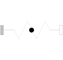
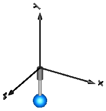
In the following figure a typical animation is shown where a mass is hanging on a damper.
Extends from Modelica.Mechanics.MultiBody.Interfaces.PartialLineForce (Base model for massless line force elements) and Modelica.Thermal.HeatTransfer.Interfaces.PartialElementaryConditionalHeatPort (Partial model to include a conditional HeatPort in order to dissipate losses, used for textual modeling, i.e., for elementary models).
| Type | Name | Default | Description |
|---|---|---|---|
Boolean | animation | true | = true, if animation shall be enabled |
TranslationalDampingConstant | d | Damping constant | |
Distance | length_a | world.defaultForceLength | Length of cylinder at frame_a side |
Distance | s_small | 1e-10 | Prevent zero-division if distance between frame_a and frame_b is zero |
Boolean | fixedRotationAtFrame_a | false | =true, if rotation frame_a.R is fixed (to directly connect line forces) |
Boolean | fixedRotationAtFrame_b | false | =true, if rotation frame_b.R is fixed (to directly connect line forces) |
Boolean | useHeatPort | false | =true, if heatPort is enabled |
final Temperature | T | 293.15 | Fixed device temperature if useHeatPort = false |
| Type | Name | Default | Description |
|---|---|---|---|
Diameter | diameter_a | world.defaultForceWidth | Diameter of cylinder at frame_a side |
Diameter | diameter_b | 0.6 * diameter_a | Diameter of cylinder at frame_b side |
Color | color_a[3] | {100, 100, 100} | Color at frame_a |
Color | color_b[3] | {155, 155, 155} | Color at frame_b |
SpecularCoefficient | specularCoefficient | world.defaultSpecularCoefficient | Reflection of ambient light (= 0: light is completely absorbed) |
| Type | Name | Description |
|---|---|---|
Frame_a | frame_a | Coordinate system a fixed to the component with one cut-force and cut-torque |
Frame_b | frame_b | Coordinate system b fixed to the component with one cut-force and cut-torque |
HeatPort_a | heatPort | Optional port to which dissipated losses are transported in form of heat |
 Model Modelica.Mechanics.MultiBody.Forces.SpringDamperParallel
Linear spring and linear damper in parallel acting as line force between frame_a and frame_b. A force f is exerted on the origin of frame_b and with opposite sign on the origin of frame_a along the line from the origin of frame_a to the origin of frame_b according to the equation:
f = c*(s - s_unstretched) + d*der(s);
where "c", "s_unstretched" and "d" are parameters, "s" is the distance between the origin of frame_a and the origin of frame_b and der(s) is the time derivative of s.
Extends from Modelica.Mechanics.MultiBody.Interfaces.PartialLineForce (Base model for massless line force elements) and Modelica.Thermal.HeatTransfer.Interfaces.PartialElementaryConditionalHeatPort (Partial model to include a conditional HeatPort in order to dissipate losses, used for textual modeling, i.e., for elementary models).
| Type | Name | Default | Description |
|---|---|---|---|
Boolean | animation | true | = true, if animation shall be enabled |
TranslationalSpringConstant | c | Spring constant | |
Length | s_unstretched | 0 | Unstretched spring length |
TranslationalDampingConstant | d | 0 | Damping constant |
Distance | length_a | world.defaultForceLength | Length of damper cylinder at frame_a side |
Integer | numberOfWindings | 5 | Number of spring windings |
Distance | s_small | 1e-10 | Prevent zero-division if distance between frame_a and frame_b is zero |
Boolean | fixedRotationAtFrame_a | false | =true, if rotation frame_a.R is fixed (to directly connect line forces) |
Boolean | fixedRotationAtFrame_b | false | =true, if rotation frame_b.R is fixed (to directly connect line forces) |
Boolean | useHeatPort | false | =true, if heatPort is enabled |
final Temperature | T | 293.15 | Fixed device temperature if useHeatPort = false |
| Type | Name | Default | Description |
|---|---|---|---|
Diameter | diameter_a | world.defaultForceWidth | Diameter of damper cylinder at frame_a side |
Diameter | diameter_b | 0.6 * diameter_a | Diameter of damper cylinder at frame_b side |
Color | color_a[3] | {100, 100, 100} | Color of damper cylinder at frame_a |
Color | color_b[3] | {155, 155, 155} | Color of damper cylinder at frame_b |
SpecularCoefficient | specularCoefficient | world.defaultSpecularCoefficient | Reflection of ambient light (= 0: light is completely absorbed) |
Distance | width | world.defaultForceWidth | Width of spring |
Distance | coilWidth | 0.1 * width | Width of spring coil |
Color | color[3] | Modelica.Mechanics.MultiBody.Types.Defaults.SpringColor | Color of spring |
| Type | Name | Description |
|---|---|---|
Frame_a | frame_a | Coordinate system a fixed to the component with one cut-force and cut-torque |
Frame_b | frame_b | Coordinate system b fixed to the component with one cut-force and cut-torque |
HeatPort_a | heatPort | Optional port to which dissipated losses are transported in form of heat |
 Model Modelica.Mechanics.MultiBody.Forces.SpringDamperSeries
Linear spring and linear damper in series connection acting as line force between frame_a and frame_b:
  frame_a --> damper ----> spring --> frame_b
          |              |
          |-- s_damper --|  (s_damper is the state variable of this system)
A force f is exerted on the origin of frame_b and with opposite sign on the origin of frame_a along the line from the origin of frame_a to the origin of frame_b according to the equations:
   f = c*(s - s_unstretched - s_damper);
   f = d*der(s_damper);
where "c", "s_unstretched" and "d" are parameters, "s" is the distance between the origin of frame_a and the origin of frame_b. "s_damper" is the length of the damper (= an internal state of this force element) and der(s_damper) is the time derivative of s_damper.
Extends from Modelica.Mechanics.MultiBody.Interfaces.PartialLineForce (Base model for massless line force elements) and Modelica.Thermal.HeatTransfer.Interfaces.PartialElementaryConditionalHeatPort (Partial model to include a conditional HeatPort in order to dissipate losses, used for textual modeling, i.e., for elementary models).
| Type | Name | Default | Description |
|---|---|---|---|
Boolean | animation | true | = true, if animation shall be enabled |
TranslationalSpringConstant | c | Spring constant | |
Length | s_unstretched | 0 | Unstretched spring length |
TranslationalDampingConstant | d | 0 | Damping constant |
Length | s_damper_start | 0 | Initial length of damper |
Distance | length_a | world.defaultForceLength | Length of damper cylinder at frame_a side |
Integer | numberOfWindings | 5 | Number of spring windings |
Distance | s_small | 1e-10 | Prevent zero-division if distance between frame_a and frame_b is zero |
Boolean | fixedRotationAtFrame_a | false | =true, if rotation frame_a.R is fixed (to directly connect line forces) |
Boolean | fixedRotationAtFrame_b | false | =true, if rotation frame_b.R is fixed (to directly connect line forces) |
Boolean | useHeatPort | false | =true, if heatPort is enabled |
final Temperature | T | 293.15 | Fixed device temperature if useHeatPort = false |
| Type | Name | Default | Description |
|---|---|---|---|
Diameter | diameter_a | world.defaultForceWidth | Diameter of damper cylinder at frame_a side |
Diameter | diameter_b | 0.6 * diameter_a | Diameter of damper cylinder at damper-spring side |
Color | color_a[3] | {100, 100, 100} | Color of damper cylinder at frame_a |
Color | color_b[3] | {155, 155, 155} | Color of damper cylinder at damper-spring frame |
SpecularCoefficient | specularCoefficient | world.defaultSpecularCoefficient | Reflection of ambient light (= 0: light is completely absorbed) |
Distance | width | world.defaultForceWidth | Width of spring |
Distance | coilWidth | 0.1 * width | Width of spring coil |
Color | color[3] | Modelica.Mechanics.MultiBody.Types.Defaults.SpringColor | Color of spring |
| Type | Name | Description |
|---|---|---|
Frame_a | frame_a | Coordinate system a fixed to the component with one cut-force and cut-torque |
Frame_b | frame_b | Coordinate system b fixed to the component with one cut-force and cut-torque |
HeatPort_a | heatPort | Optional port to which dissipated losses are transported in form of heat |