 Package Modelica.Mechanics.Rotational.Components
Components for 1D rotational mechanical drive trains
Package Modelica.Mechanics.Rotational.Components
This package contains basic components 1D mechanical rotational drive trains.
Extends from Modelica.Icons.Package (Icon for standard packages).
| Name | Description |
|---|---|
AngleToTorqueAdaptor | Signal adaptor for a Rotational flange with torque as output and angle, speed, and optionally acceleration as inputs (especially useful for FMUs) |
BearingFriction | Coulomb friction in bearings |
Brake | Brake based on Coulomb friction |
Clutch | Clutch based on Coulomb friction |
Damper | Linear 1D rotational damper |
Disc | 1-dim. rotational rigid component without inertia, where right flange is rotated by a fixed angle with respect to left flange |
ElastoBacklash | Backlash connected in series to linear spring and damper (backlash is modeled with elasticity) |
ElastoBacklash2 | Backlash connected in series to linear spring and damper (backlash is modeled with elasticity; at start of contact the flange torque can jump, contrary to the ElastoBacklash model) |
Fixed | Flange fixed in housing at a given angle |
Gearbox | Realistic model of a gearbox (based on LossyGear) |
GeneralAngleToTorqueAdaptor | Signal adaptor for a rotational flange with torque as output and angle, speed and acceleration as input (especially useful for FMUs) |
GeneralTorqueToAngleAdaptor | Signal adaptor for a rotational flange with angle, speed, and acceleration as outputs and torque as input (especially useful for FMUs) |
IdealGear | Ideal gear without inertia |
IdealGearR2T | Gearbox transforming rotational into translational motion |
IdealPlanetary | Ideal planetary gear box |
IdealRollingWheel | Simple 1-dim. model of an ideal rolling wheel without inertia |
Inertia | 1D-rotational component with inertia |
InitializeFlange | Initializes a flange with pre-defined angle, speed and angular acceleration (usually, this is reference data from a control bus) |
LossyGear | Gear with mesh efficiency and bearing friction (stuck/rolling possible) |
OneWayClutch | Parallel connection of freewheel and clutch |
RelativeStates | Definition of relative state variables |
Spring | Linear 1D rotational spring |
SpringDamper | Linear 1D rotational spring and damper in parallel |
TorqueToAngleAdaptor | Signal adaptor for a Rotational flange with angle, speed, and acceleration as outputs and torque as input (especially useful for FMUs) |
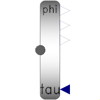
 Model Modelica.Mechanics.Rotational.Components.Fixed
The flange of a 1D rotational mechanical system is fixed at an angle phi0 in the housing. May be used:
| Type | Name | Default | Description |
|---|---|---|---|
Angle | phi0 | 0 | Fixed offset angle of housing |
| Type | Name | Description |
|---|---|---|
Flange_b | flange | (right) flange fixed in housing |
 Model Modelica.Mechanics.Rotational.Components.Inertia
Rotational component with inertia and two rigidly connected flanges.
Extends from Modelica.Mechanics.Rotational.Interfaces.PartialTwoFlanges (Partial model for a component with two rotational 1-dim. shaft flanges).
| Type | Name | Default | Description |
|---|---|---|---|
Inertia | J | Moment of inertia | |
StateSelect | stateSelect | StateSelect.default | Priority to use phi and w as states |
| Type | Name | Description |
|---|---|---|
Flange_a | flange_a | Flange of left shaft |
Flange_b | flange_b | Flange of right shaft |
 Model Modelica.Mechanics.Rotational.Components.Disc
Rotational component with two rigidly connected flanges without inertia. The right flange is rotated by the fixed angle "deltaPhi" with respect to the left flange.
Extends from Modelica.Mechanics.Rotational.Interfaces.PartialTwoFlanges (Partial model for a component with two rotational 1-dim. shaft flanges).
| Type | Name | Default | Description |
|---|---|---|---|
Angle | deltaPhi | 0 | Fixed rotation of left flange with respect to right flange (= flange_b.phi - flange_a.phi) |
| Type | Name | Description |
|---|---|---|
Flange_a | flange_a | Flange of left shaft |
Flange_b | flange_b | Flange of right shaft |
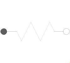 Model Modelica.Mechanics.Rotational.Components.Spring
A linear 1D rotational spring. The component can be connected either between two inertias/gears to describe the shaft elasticity, or between a inertia/gear and the housing (component Fixed), to describe a coupling of the element with the housing via a spring.
Extends from Modelica.Mechanics.Rotational.Interfaces.PartialCompliant (Partial model for the compliant connection of two rotational 1-dim. shaft flanges).
| Type | Name | Default | Description |
|---|---|---|---|
RotationalSpringConstant | c | Spring constant | |
Angle | phi_rel0 | 0 | Unstretched spring angle |
| Type | Name | Description |
|---|---|---|
Flange_a | flange_a | Left flange of compliant 1-dim. rotational component |
Flange_b | flange_b | Right flange of compliant 1-dim. rotational component |
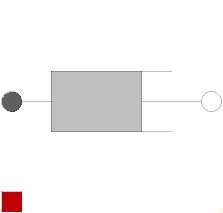 Model Modelica.Mechanics.Rotational.Components.Damper
Linear, velocity dependent damper element. It can be either connected between an inertia or gear and the housing (component Fixed), or between two inertia/gear elements.
See also the discussion State Selection in the User's Guide of the Rotational library.
Extends from Modelica.Mechanics.Rotational.Interfaces.PartialCompliantWithRelativeStates (Partial model for the compliant connection of two rotational 1-dim. shaft flanges where the relative angle and speed are used as preferred states) and Modelica.Thermal.HeatTransfer.Interfaces.PartialElementaryConditionalHeatPortWithoutT (Partial model to include a conditional HeatPort in order to dissipate losses, used for textual modeling, i.e., for elementary models).
| Type | Name | Default | Description |
|---|---|---|---|
Angle | phi_nominal | 1e-4 | Nominal value of phi_rel (used for scaling) |
StateSelect | stateSelect | StateSelect.prefer | Priority to use phi_rel and w_rel as states |
RotationalDampingConstant | d | Damping constant | |
Boolean | useHeatPort | false | =true, if heatPort is enabled |
| Type | Name | Description |
|---|---|---|
Flange_a | flange_a | Left flange of compliant 1-dim. rotational component |
Flange_b | flange_b | Right flange of compliant 1-dim. rotational component |
HeatPort_a | heatPort | Optional port to which dissipated losses are transported in form of heat |
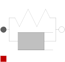 Model Modelica.Mechanics.Rotational.Components.SpringDamper
A spring and damper element connected in parallel. The component can be connected either between two inertias/gears to describe the shaft elasticity and damping, or between an inertia/gear and the housing (component Fixed), to describe a coupling of the element with the housing via a spring/damper.
See also the discussion State Selection in the User's Guide of the Rotational library.
Extends from Modelica.Mechanics.Rotational.Interfaces.PartialCompliantWithRelativeStates (Partial model for the compliant connection of two rotational 1-dim. shaft flanges where the relative angle and speed are used as preferred states) and Modelica.Thermal.HeatTransfer.Interfaces.PartialElementaryConditionalHeatPortWithoutT (Partial model to include a conditional HeatPort in order to dissipate losses, used for textual modeling, i.e., for elementary models).
| Type | Name | Default | Description |
|---|---|---|---|
RotationalSpringConstant | c | Spring constant | |
RotationalDampingConstant | d | Damping constant | |
Angle | phi_rel0 | 0 | Unstretched spring angle |
Angle | phi_nominal | 1e-4 | Nominal value of phi_rel (used for scaling) |
StateSelect | stateSelect | StateSelect.prefer | Priority to use phi_rel and w_rel as states |
Boolean | useHeatPort | false | =true, if heatPort is enabled |
| Type | Name | Description |
|---|---|---|
Flange_a | flange_a | Left flange of compliant 1-dim. rotational component |
Flange_b | flange_b | Right flange of compliant 1-dim. rotational component |
HeatPort_a | heatPort | Optional port to which dissipated losses are transported in form of heat |
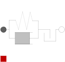 Model Modelica.Mechanics.Rotational.Components.ElastoBacklash
This element consists of a backlash element connected in series to a spring and damper element which are connected in parallel. The spring constant shall be non-zero, otherwise the component cannot be used.
In combination with components IdealGear, the ElastoBacklash model can be used to model a gear box with backlash, elasticity and damping.
During initialization, the backlash characteristic is replaced by a continuous approximation in the backlash region, in order to reduce problems during initialization, especially for inverse models.
If the backlash b is smaller as 1e-10 rad (especially, if b=0), then the backlash is ignored and the component reduces to a spring/damper element in parallel.
In the backlash region (-b/2 ≤ flange_b.phi - flange_a.phi - phi_rel0 ≤ b/2) no torque is exerted (flange_b.tau = 0). Outside of this region, contact is present and the contact torque is basically computed with a linear spring/damper characteristic:
   desiredContactTorque = c*phi_contact + d*der(phi_contact)

            phi_contact = phi_rel - phi_rel0 - b/2 if phi_rel - phi_rel0 >  b/2
                        = phi_rel - phi_rel0 + b/2 if phi_rel - phi_rel0 < -b/2

            phi_rel     = flange_b.phi - flange_a.phi;
This torque characteristic leads to the following difficulties:
In the literature there are several proposals to fix problem (2). However, there seems to be no proposal to avoid sticking. For this reason, the most simple approach is used in the ElastoBacklash model, to fix both problems by slight changes to the linear spring/damper characteristic:
// Torque characteristic when phi_rel > phi_rel0
if phi_rel - phi_rel0 < b/2 then
tau_c = 0; // spring torque
tau_d = 0; // damper torque
flange_b.tau = 0;
else
tau_c = c*(phi_rel - phi_rel0); // spring torque
tau_d = d*der(phi_rel); // damper torque
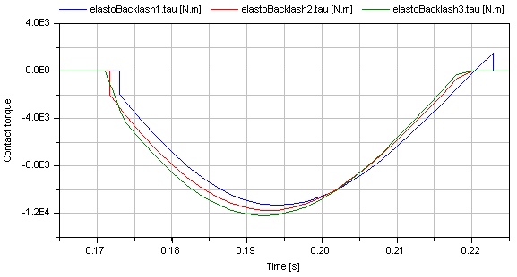
flange_b.tau = if tau_c + tau_d ≤ 0 then 0 else tau_c + min( tau_c, tau_d );
end if;
Note, when sticking would occur (tau_c + tau_d ≤ 0), then the contact torque is explicitly set to zero. The "min(tau_c, tau_d)" part in the if-expression, limits the damping torque when it is pushing. This means that at the start of the contact (phi_rel - phi_rel0 = b/2), the damping torque is zero and is continuous. The effect of both modifications is that the absolute value of the damping torque is always limited by the absolute value of the spring torque: |tau_d| ≤ |tau_c|.
In the next figure, a typical simulation with the ElastoBacklash model is shown (Examples.Backlash) where the different effects are visualized:
See also the discussion State Selection in the User's Guide of the Rotational library.
Extends from Modelica.Mechanics.Rotational.Interfaces.PartialCompliantWithRelativeStates (Partial model for the compliant connection of two rotational 1-dim. shaft flanges where the relative angle and speed are used as preferred states) and Modelica.Thermal.HeatTransfer.Interfaces.PartialElementaryConditionalHeatPortWithoutT (Partial model to include a conditional HeatPort in order to dissipate losses, used for textual modeling, i.e., for elementary models).
| Type | Name | Default | Description |
|---|---|---|---|
RotationalSpringConstant | c | Spring constant (c > 0 required) | |
RotationalDampingConstant | d | Damping constant | |
Angle | b | 0 | Total backlash |
Angle | phi_rel0 | 0 | Unstretched spring angle |
Angle | phi_nominal | 1e-4 | Nominal value of phi_rel (used for scaling) |
StateSelect | stateSelect | StateSelect.prefer | Priority to use phi_rel and w_rel as states |
Boolean | useHeatPort | false | =true, if heatPort is enabled |
| Type | Name | Description |
|---|---|---|
Flange_a | flange_a | Left flange of compliant 1-dim. rotational component |
Flange_b | flange_b | Right flange of compliant 1-dim. rotational component |
HeatPort_a | heatPort | Optional port to which dissipated losses are transported in form of heat |
 Model Modelica.Mechanics.Rotational.Components.ElastoBacklash2
This element consists of a backlash element connected in series to a spring and damper element which are connected in parallel. The spring constant shall be non-zero, otherwise the component cannot be used.
In combination with components IdealGear, the ElastoBacklash2 model can be used to model a gear box with backlash, elasticity and damping.
During initialization, the backlash characteristic is replaced by a continuous approximation in the backlash region, in order to reduce problems during initialization, especially for inverse models.
If the backlash b is smaller as 1e-10 rad (especially, if b=0), then the backlash is ignored and the component reduces to a spring/damper element in parallel.
In the backlash region (-b/2 ≤ flange_b.phi - flange_a.phi - phi_rel0 ≤ b/2) no torque is exerted (flange_b.tau = 0). Outside of this region, contact is present and the contact torque is basically computed with a linear spring/damper characteristic:
   desiredContactTorque = c*phi_contact + d*der(phi_contact)

            phi_contact = phi_rel - phi_rel0 - b/2 if phi_rel - phi_rel0 >  b/2
                        = phi_rel - phi_rel0 + b/2 if phi_rel - phi_rel0 < -b/2

            phi_rel     = flange_b.phi - flange_a.phi;
This torque characteristic leads to the following difficulty:
In the literature this issue seems to be not discussed. For this reason, the most simple approach is used in the ElastoBacklash2 model, by slightly changing the linear spring/damper characteristic to:
    // Torque characteristic when phi_rel > phi_rel0
    if phi_rel - phi_rel0 < b/2 then
       tau_c = 0;          // spring torque
       tau_d = 0;          // damper torque
       flange_b.tau = 0;
    else
       tau_c = c*(phi_rel - phi_rel0);    // spring torque
       tau_d = d*der(phi_rel);            // damper torque
       flange_b.tau = if tau_c + tau_d ≤ 0 then 0 else tau_c + tau_d;
    end if;
Note, when sticking would occur (tau_c + tau_d ≤ 0), then the contact torque is explicitly set to zero.
This model of backlash is slightly different to the ElastoBacklash component:
See also the discussion State Selection in the User's Guide of the Rotational library.
Extends from Modelica.Mechanics.Rotational.Interfaces.PartialCompliantWithRelativeStates (Partial model for the compliant connection of two rotational 1-dim. shaft flanges where the relative angle and speed are used as preferred states) and Modelica.Thermal.HeatTransfer.Interfaces.PartialElementaryConditionalHeatPortWithoutT (Partial model to include a conditional HeatPort in order to dissipate losses, used for textual modeling, i.e., for elementary models).
| Type | Name | Default | Description |
|---|---|---|---|
RotationalSpringConstant | c | Spring constant (c > 0 required) | |
RotationalDampingConstant | d | Damping constant | |
Angle | b | 0 | Total backlash |
Angle | phi_rel0 | 0 | Unstretched spring angle |
Angle | phi_nominal | 1e-4 | Nominal value of phi_rel (used for scaling) |
StateSelect | stateSelect | StateSelect.prefer | Priority to use phi_rel and w_rel as states |
Boolean | useHeatPort | false | =true, if heatPort is enabled |
| Type | Name | Description |
|---|---|---|
Flange_a | flange_a | Left flange of compliant 1-dim. rotational component |
Flange_b | flange_b | Right flange of compliant 1-dim. rotational component |
HeatPort_a | heatPort | Optional port to which dissipated losses are transported in form of heat |
 Model Modelica.Mechanics.Rotational.Components.BearingFriction
This element describes Coulomb friction in bearings, i.e., a frictional torque acting between a flange and the housing. The positive sliding friction torque "tau" has to be defined by table "tau_pos" as function of the absolute angular velocity "w". E.g.
       w | tau
      ---+-----
       0 |   0
       1 |   2
       2 |   5
       3 |   8
gives the following table:
tau_pos = [0, 0; 1, 2; 2, 5; 3, 8];
Currently, only linear interpolation in the table is supported. Outside of the table, extrapolation through the last two table entries is used. It is assumed that the negative sliding friction force has the same characteristic with negative values. Friction is modelled in the following way:
When the absolute angular velocity "w" is not zero, the friction torque is a function of w and of a constant normal force. This dependency is defined via table tau_pos and can be determined by measurements, e.g., by driving the gear with constant velocity and measuring the needed motor torque (= friction torque).
When the absolute angular velocity becomes zero, the elements connected by the friction element become stuck, i.e., the absolute angle remains constant. In this phase the friction torque is calculated from a torque balance due to the requirement, that the absolute acceleration shall be zero. The elements begin to slide when the friction torque exceeds a threshold value, called the maximum static friction torque, computed via:
maximum_static_friction = peak * sliding_friction(w=0) (peak >= 1)
This procedure is implemented in a "clean" way by state events and leads to continuous/discrete systems of equations if friction elements are dynamically coupled which have to be solved by appropriate numerical methods. The method is described in (see also a short sketch in UsersGuide.ModelingOfFriction):
More precise friction models take into account the elasticity of the material when the two elements are "stuck", as well as other effects, like hysteresis. This has the advantage that the friction element can be completely described by a differential equation without events. The drawback is that the system becomes stiff (about 10-20 times slower simulation) and that more material constants have to be supplied which requires more sophisticated identification. For more details, see the following references, especially (Armstrong and Canudas de Wit 1996):
Extends from Modelica.Mechanics.Rotational.Interfaces.PartialElementaryTwoFlangesAndSupport2 (Partial model for a component with two rotational 1-dim. shaft flanges and a support used for textual modeling, i.e., for elementary models), Modelica.Mechanics.Rotational.Interfaces.PartialFriction (Partial model of Coulomb friction elements), and Modelica.Thermal.HeatTransfer.Interfaces.PartialElementaryConditionalHeatPortWithoutT (Partial model to include a conditional HeatPort in order to dissipate losses, used for textual modeling, i.e., for elementary models).
| Type | Name | Default | Description |
|---|---|---|---|
Boolean | useSupport | false | = true, if support flange enabled, otherwise implicitly grounded |
Real | tau_pos[:,2] | [0,1] | [w,tau] Positive sliding friction characteristic (w>=0) |
Real | peak | 1 | Peak for maximum friction torque at w==0 (tau0_max = peak*tau_pos[1,2]) |
AngularVelocity | w_small | 1e+10 | Relative angular velocity near to zero if jumps due to a reinit(..) of the velocity can occur (set to low value only if such impulses can occur) |
Real | K_locked | 0 | Gain driving the relative motion between the friction elements to 0 when locked. This parameter should only be non-zero when using the model with fixed-step integration |
Boolean | useHeatPort | false | =true, if heatPort is enabled |
| Type | Name | Description |
|---|---|---|
Flange_a | flange_a | Flange of left shaft |
Flange_b | flange_b | Flange of right shaft |
Support | support | Support/housing of component |
HeatPort_a | heatPort | Optional port to which dissipated losses are transported in form of heat |
 Model Modelica.Mechanics.Rotational.Components.Brake
This component models a brake, i.e., a component where a frictional torque is acting between the housing and a flange and a controlled normal force presses the flange to the housing in order to increase friction. The normal force fn has to be provided as input signal f_normalized in a normalized form (0 ≤ f_normalized ≤ 1), fn = fn_max*f_normalized, where fn_max has to be provided as parameter. Friction in the brake is modelled in the following way:
When the absolute angular velocity "w" is not zero, the friction torque is a function of the velocity dependent friction coefficient mue(w) , of the normal force "fn", and of a geometry constant "cgeo" which takes into account the geometry of the device and the assumptions on the friction distributions:
frictional_torque = cgeo * mue(w) * fn
Typical values of coefficients of friction:
      dry operation   :  mue = 0.2 .. 0.4
      operating in oil:  mue = 0.05 .. 0.1
When plates are pressed together, where ri is the inner radius, ro is the outer radius and N is the number of friction interfaces, the geometry constant is calculated in the following way under the assumption of a uniform rate of wear at the interfaces:
cgeo = N*(r0 + ri)/2
The positive part of the friction characteristic mue(w), w >= 0, is defined via table mue_pos (first column = w, second column = mue). Currently, only linear interpolation in the table is supported.
When the absolute angular velocity becomes zero, the elements connected by the friction element become stuck, i.e., the absolute angle remains constant. In this phase the friction torque is calculated from a torque balance due to the requirement, that the absolute acceleration shall be zero. The elements begin to slide when the friction torque exceeds a threshold value, called the maximum static friction torque, computed via:
frictional_torque = peak * cgeo * mue(w=0) * fn (peak >= 1)
This procedure is implemented in a "clean" way by state events and leads to continuous/discrete systems of equations if friction elements are dynamically coupled. The method is described in (see also a short sketch in UsersGuide.ModelingOfFriction):
More precise friction models take into account the elasticity of the material when the two elements are "stuck", as well as other effects, like hysteresis. This has the advantage that the friction element can be completely described by a differential equation without events. The drawback is that the system becomes stiff (about 10-20 times slower simulation) and that more material constants have to be supplied which requires more sophisticated identification. For more details, see the following references, especially (Armstrong and Canudas de Wit 1996):
See also the discussion State Selection in the User's Guide of the Rotational library.
Extends from Modelica.Mechanics.Rotational.Interfaces.PartialElementaryTwoFlangesAndSupport2 (Partial model for a component with two rotational 1-dim. shaft flanges and a support used for textual modeling, i.e., for elementary models), Modelica.Mechanics.Rotational.Interfaces.PartialFriction (Partial model of Coulomb friction elements), and Modelica.Thermal.HeatTransfer.Interfaces.PartialElementaryConditionalHeatPortWithoutT (Partial model to include a conditional HeatPort in order to dissipate losses, used for textual modeling, i.e., for elementary models).
| Type | Name | Default | Description |
|---|---|---|---|
Boolean | useSupport | false | = true, if support flange enabled, otherwise implicitly grounded |
Real | mue_pos[:,2] | [0,0.5] | [w,mue] positive sliding friction coefficient (w_rel>=0) |
Real | peak | 1 | Peak for maximum value of mue at w==0 (mue0_max = peak*mue_pos[1,2]) |
Real | cgeo | 1 | Geometry constant containing friction distribution assumption |
Force | fn_max | Maximum normal force | |
AngularVelocity | w_small | 1e+10 | Relative angular velocity near to zero if jumps due to a reinit(..) of the velocity can occur (set to low value only if such impulses can occur) |
Real | K_locked | 0 | Gain driving the relative motion between the friction elements to 0 when locked. This parameter should only be non-zero when using the model with fixed-step integration |
Boolean | useHeatPort | false | =true, if heatPort is enabled |
| Type | Name | Description |
|---|---|---|
Flange_a | flange_a | Flange of left shaft |
Flange_b | flange_b | Flange of right shaft |
Support | support | Support/housing of component |
HeatPort_a | heatPort | Optional port to which dissipated losses are transported in form of heat |
input RealInput | f_normalized | Normalized force signal 0..1 (normal force = fn_max*f_normalized; brake is active if > 0) |
 Model Modelica.Mechanics.Rotational.Components.Clutch
This component models a clutch, i.e., a component with two flanges where friction is present between the two flanges and these flanges are pressed together via a normal force. The normal force fn has to be provided as input signal f_normalized in a normalized form (0 ≤ f_normalized ≤ 1), fn = fn_max*f_normalized, where fn_max has to be provided as parameter. Friction in the clutch is modelled in the following way:
When the relative angular velocity is not zero, the friction torque is a function of the velocity dependent friction coefficient mue(w_rel) , of the normal force "fn", and of a geometry constant "cgeo" which takes into account the geometry of the device and the assumptions on the friction distributions:
frictional_torque = cgeo * mue(w_rel) * fn
Typical values of coefficients of friction:
      dry operation   :  mue = 0.2 .. 0.4
      operating in oil:  mue = 0.05 .. 0.1
When plates are pressed together, where ri is the inner radius, ro is the outer radius and N is the number of friction interfaces, the geometry constant is calculated in the following way under the assumption of a uniform rate of wear at the interfaces:
cgeo = N*(r0 + ri)/2
The positive part of the friction characteristic mue(w_rel), w_rel >= 0, is defined via table mue_pos (first column = w_rel, second column = mue). Currently, only linear interpolation in the table is supported.
When the relative angular velocity becomes zero, the elements connected by the friction element become stuck, i.e., the relative angle remains constant. In this phase the friction torque is calculated from a torque balance due to the requirement, that the relative acceleration shall be zero. The elements begin to slide when the friction torque exceeds a threshold value, called the maximum static friction torque, computed via:
frictional_torque = peak * cgeo * mue(w_rel=0) * fn (peak >= 1)
This procedure is implemented in a "clean" way by state events and leads to continuous/discrete systems of equations if friction elements are dynamically coupled. The method is described in (see also a short sketch in UsersGuide.ModelingOfFriction):
More precise friction models take into account the elasticity of the material when the two elements are "stuck", as well as other effects, like hysteresis. This has the advantage that the friction element can be completely described by a differential equation without events. The drawback is that the system becomes stiff (about 10-20 times slower simulation) and that more material constants have to be supplied which requires more sophisticated identification. For more details, see the following references, especially (Armstrong and Canudas de Wit 1996):
See also the discussion State Selection in the User's Guide of the Rotational library.
Extends from Modelica.Mechanics.Rotational.Icons.Clutch (Icon of a clutch), Modelica.Mechanics.Rotational.Interfaces.PartialCompliantWithRelativeStates (Partial model for the compliant connection of two rotational 1-dim. shaft flanges where the relative angle and speed are used as preferred states), Modelica.Mechanics.Rotational.Interfaces.PartialFriction (Partial model of Coulomb friction elements), and Modelica.Thermal.HeatTransfer.Interfaces.PartialElementaryConditionalHeatPortWithoutT (Partial model to include a conditional HeatPort in order to dissipate losses, used for textual modeling, i.e., for elementary models).
| Type | Name | Default | Description |
|---|---|---|---|
Angle | phi_nominal | 1e-4 | Nominal value of phi_rel (used for scaling) |
StateSelect | stateSelect | StateSelect.prefer | Priority to use phi_rel and w_rel as states |
Real | mue_pos[:,2] | [0,0.5] | [w,mue] positive sliding friction coefficient (w_rel>=0) |
Real | peak | 1 | Peak for maximum value of mue at w==0 (mue0_max = peak*mue_pos[1,2]) |
Real | cgeo | 1 | Geometry constant containing friction distribution assumption |
Force | fn_max | Maximum normal force | |
AngularVelocity | w_small | 1e+10 | Relative angular velocity near to zero if jumps due to a reinit(..) of the velocity can occur (set to low value only if such impulses can occur) |
Real | K_locked | 0 | Gain driving the relative motion between the friction elements to 0 when locked. This parameter should only be non-zero when using the model with fixed-step integration |
Boolean | useHeatPort | false | =true, if heatPort is enabled |
| Type | Name | Description |
|---|---|---|
Flange_a | flange_a | Left flange of compliant 1-dim. rotational component |
Flange_b | flange_b | Right flange of compliant 1-dim. rotational component |
HeatPort_a | heatPort | Optional port to which dissipated losses are transported in form of heat |
input RealInput | f_normalized | Normalized force signal 0..1 (normal force = fn_max*f_normalized; clutch is engaged if > 0) |
 Model Modelica.Mechanics.Rotational.Components.OneWayClutch
This component models a one-way clutch, i.e., a component with two flanges where friction is present between the two flanges and these flanges are pressed together via a normal force. These flanges may be sliding with respect to each other.
A one-way-clutch is an element where a clutch is connected in parallel to a free wheel. This special element is provided, because such a parallel connection introduces an ambiguity into the model (the constraint torques are not uniquely defined when both elements are stuck) and this element resolves it by introducing one constraint torque only instead of two constraints.
Note, initial values have to be chosen for the model such that the relative speed of the one-way-clutch ≥ 0. Otherwise, the configuration is physically not possible and an error occurs.
The normal force fn has to be provided as input signal f_normalized in a normalized form (0 ≤ f_normalized ≤ 1), fn = fn_max * f_normalized, where fn_max has to be provided as parameter.
The friction in the clutch is modeled in the following way. When the relative angular velocity is positive, the friction torque is a function of the velocity dependent friction coefficient mue(w_rel), of the normal force fn, and of a geometry constant cgeo which takes into account the geometry of the device and the assumptions on the friction distributions:
frictional_torque = cgeo * mue(w_rel) * fn
Typical values of coefficients of friction:
dry operation   :  mue = 0.2 .. 0.4
operating in oil:  mue = 0.05 .. 0.1
The geometry constant is calculated - under the assumption of a uniform rate of wear at the friction surfaces - in the following way:
cgeo = N*(r0 + ri)/2
where ri is the inner radius, ro is the outer radius and N is the number of friction interfaces,
The positive part of the friction characteristic mue(w_rel), w_rel >= 0, is defined via table mue_pos (first column = w_rel, second column = mue). Currently, only linear interpolation in the table is supported.
When the relative angular velocity w_rel becomes zero, the elements connected by the friction element become stuck, i.e., the relative angle remains constant. In this phase the friction torque is calculated from a torque balance due to the requirement that the relative acceleration shall be zero. The elements begin to slide when the friction torque exceeds a threshold value, called the maximum static friction torque, computed via:
frictional_torque = peak * cgeo * mue(w_rel=0) * fn, (peak >= 1)
This procedure is implemented in a "clean" way by state events and leads to continuous/discrete systems of equations if friction elements are dynamically coupled. The method is described in (see also a short sketch in UsersGuide.ModelingOfFriction):
See also the discussion State Selection in the User's Guide of the Rotational library.
Extends from Modelica.Mechanics.Rotational.Icons.Clutch (Icon of a clutch), Modelica.Mechanics.Rotational.Interfaces.PartialCompliantWithRelativeStates (Partial model for the compliant connection of two rotational 1-dim. shaft flanges where the relative angle and speed are used as preferred states), and Modelica.Thermal.HeatTransfer.Interfaces.PartialElementaryConditionalHeatPortWithoutT (Partial model to include a conditional HeatPort in order to dissipate losses, used for textual modeling, i.e., for elementary models).
| Type | Name | Default | Description |
|---|---|---|---|
Angle | phi_nominal | 1e-4 | Nominal value of phi_rel (used for scaling) |
StateSelect | stateSelect | StateSelect.prefer | Priority to use phi_rel and w_rel as states |
Real | mue_pos[:,2] | [0,0.5] | [w,mue] positive sliding friction coefficient (w_rel>=0) |
Real | peak | 1 | Peak for maximum value of mue at w==0 (mue0_max = peak*mue_pos[1,2]) |
Real | cgeo | 1 | Geometry constant containing friction distribution assumption |
Force | fn_max | Maximum normal force | |
AngularVelocity | w_small | 1e+10 | Relative angular velocity near to zero if jumps due to a reinit(..) of the velocity can occur (set to low value only if such impulses can occur) |
Boolean | useHeatPort | false | =true, if heatPort is enabled |
| Type | Name | Description |
|---|---|---|
Flange_a | flange_a | Left flange of compliant 1-dim. rotational component |
Flange_b | flange_b | Right flange of compliant 1-dim. rotational component |
HeatPort_a | heatPort | Optional port to which dissipated losses are transported in form of heat |
input RealInput | f_normalized | Normalized force signal 0..1 (normal force = fn_max*f_normalized; clutch is engaged if > 0) |
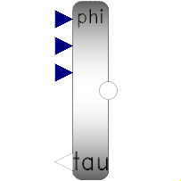
 Model Modelica.Mechanics.Rotational.Components.IdealGear
This element characterizes any type of gear box which is fixed in the ground and which has one driving shaft and one driven shaft. The gear is ideal, i.e., it does not have inertia, elasticity, damping or backlash. If these effects have to be considered, the gear has to be connected to other elements in an appropriate way.
Extends from Modelica.Mechanics.Rotational.Icons.Gear (Icon of a rotational gear) and Modelica.Mechanics.Rotational.Interfaces.PartialElementaryTwoFlangesAndSupport2 (Partial model for a component with two rotational 1-dim. shaft flanges and a support used for textual modeling, i.e., for elementary models).
| Type | Name | Default | Description |
|---|---|---|---|
Boolean | useSupport | false | = true, if support flange enabled, otherwise implicitly grounded |
Real | ratio | Transmission ratio (flange_a.phi/flange_b.phi) |
| Type | Name | Description |
|---|---|---|
Flange_a | flange_a | Flange of left shaft |
Flange_b | flange_b | Flange of right shaft |
Support | support | Support/housing of component |
 Model Modelica.Mechanics.Rotational.Components.LossyGear
This component models the gear ratio and the losses of a standard gear box in a reliable way including the stuck phases that may occur at zero speed. The gear boxes that can be handled are fixed in the ground or on a moving support, have one input and one output shaft, and are essentially described by the equations:
             flange_a.phi  = i*flange_b.phi;
-(flange_b.tau - tau_bf_b) = i*eta_mf*(flange_a.tau - tau_bf_a);

// or        -flange_b.tau = i*eta_mf*(flange_a.tau - tau_bf_a - tau_bf_b/(i*eta_mf));
where
The loss terms "eta_mf", "tau_bf_a" and "tau_bf_b" are functions of the absolute value of the input shaft speed w_a and of the energy flow direction. They are defined by parameter lossTable[:,5] where the columns of this table have the following meaning:
| |w_a| | eta_mf1 | eta_mf2 | |tau_bf1| | |tau_bf2| |
| ... | ... | ... | ... | ... |
| ... | ... | ... | ... | ... |
with
| |w_a| | Absolute value of angular velocity of input shaft flange_a |
| eta_mf1 | Mesh efficiency in case that flange_a is driving |
| eta_mf2 | Mesh efficiency in case that flange_b is driving |
| |tau_bf1| | Absolute resultant bearing friction torque with respect to flange_a
in case that flange_a is driving (= |tau_bf_a*eta_mf1 + tau_bf_b/i|) |
| |tau_bf2| | Absolute resultant bearing friction torque with respect to flange_a
in case that flange_b is driving (= |tau_bf_a/eta_mf2 + tau_bf_b/i|) |
With these variables, the mesh efficiency and the bearing friction are formally defined as:
if (flange_a.tau - tau_bf_a)*w_a > 0 or
   (flange_a.tau - tau_bf_a) == 0 and w_a > 0 then
   eta_mf := eta_mf1
   tau_bf := tau_bf1
elseif (flange_a.tau - tau_bf_a)*w_a < 0 or
       (flange_a.tau - tau_bf_a) == 0 and w_a < 0 then
   eta_mf := 1/eta_mf2
   tau_bf := tau_bf2
else // w_a == 0
   eta_mf and tau_bf are computed such that der(w_a) = 0
end if;
-flange_b.tau = i*(eta_mf*flange_a.tau - tau_bf);
Note, that the losses are modeled in a physically meaningful way taking into account that at zero speed the movement may be locked due to the friction in the gear teeth and/or in the bearings. Due to this important property, this component can be used in situations where the combination of the components Modelica.Mechanics.Rotational.IdealGear and Modelica.Mechanics.Rotational.GearEfficiency will fail because, e.g., chattering occurs when using the Modelica.Mechanics.Rotational.GearEfficiency model.
Extends from Modelica.Mechanics.Rotational.Icons.Gear (Icon of a rotational gear), Modelica.Mechanics.Rotational.Interfaces.PartialElementaryTwoFlangesAndSupport2 (Partial model for a component with two rotational 1-dim. shaft flanges and a support used for textual modeling, i.e., for elementary models), and Modelica.Thermal.HeatTransfer.Interfaces.PartialElementaryConditionalHeatPortWithoutT (Partial model to include a conditional HeatPort in order to dissipate losses, used for textual modeling, i.e., for elementary models).
| Type | Name | Default | Description |
|---|---|---|---|
Boolean | useSupport | false | = true, if support flange enabled, otherwise implicitly grounded |
Real | ratio | Transmission ratio (flange_a.phi/flange_b.phi) | |
Real | lossTable[:,5] | [0,1,1,0,0] | Array for mesh efficiencies and bearing friction depending on speed |
Boolean | useHeatPort | false | =true, if heatPort is enabled |
| Type | Name | Description |
|---|---|---|
Flange_a | flange_a | Flange of left shaft |
Flange_b | flange_b | Flange of right shaft |
Support | support | Support/housing of component |
HeatPort_a | heatPort | Optional port to which dissipated losses are transported in form of heat |
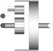 Model Modelica.Mechanics.Rotational.Components.IdealPlanetary
The IdealPlanetary gear box is an ideal gear without inertia, elasticity, damping or backlash consisting of an inner sun wheel, an outer ring wheel and a planet wheel located between sun and ring wheel. The bearing of the planet wheel shaft is fixed in the planet carrier. The component can be connected to other elements at the sun, ring and/or carrier flanges. It is not possible to connect to the planet wheel. If inertia shall not be neglected, the sun, ring and carrier inertias can be easily added by attaching inertias (= model Inertia) to the corresponding connectors. The inertias of the planet wheels are always neglected.
The icon of the planetary gear signals that the sun and carrier flanges are on the left side and the ring flange is on the right side of the gear box. However, this component is generic and is valid independently how the flanges are actually placed (e.g., sun wheel may be placed on the right side instead on the left side in reality).
The ideal planetary gearbox is uniquely defined by the ratio of the number of ring teeth zr with respect to the number of sun teeth zs. For example, if there are 100 ring teeth and 50 sun teeth then ratio = zr/zs = 2. The number of planet teeth zp has to fulfill the following relationship:
zp := (zr - zs) / 2
Therefore, in the above example zp = 25 is required.
According to the overall convention, the positive direction of all vectors, especially the absolute angular velocities and cut-torques in the flanges, are along the axis vector displayed in the icon.
| Type | Name | Default | Description |
|---|---|---|---|
Real | ratio | Number of ring_teeth/sun_teeth (e.g., ratio=100/50) |
| Type | Name | Description |
|---|---|---|
Flange_a | sun | Flange of sun shaft |
Flange_a | carrier | Flange of carrier shaft |
Flange_b | ring | Flange of ring shaft |
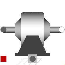 Model Modelica.Mechanics.Rotational.Components.Gearbox
This component models the essential effects of a gearbox, in particular
The inertia of the gear wheels is not modeled. If necessary, inertia has to be taken into account by connecting components of model Inertia to the left and/or the right flange of component Gearbox.
Extends from Modelica.Mechanics.Rotational.Icons.Gearbox (Icon of a gear box), Modelica.Mechanics.Rotational.Interfaces.PartialTwoFlangesAndSupport (Partial model for a component with two rotational 1-dim. shaft flanges and a support used for graphical modeling, i.e., the model is build up by drag-and-drop from elementary components), and Modelica.Thermal.HeatTransfer.Interfaces.PartialConditionalHeatPort (Partial model to include a conditional HeatPort in order to dissipate losses, used for graphical modeling, i.e., for building models by drag-and-drop).
| Type | Name | Default | Description |
|---|---|---|---|
Boolean | useSupport | false | = true, if support flange enabled, otherwise implicitly grounded |
Real | ratio | Transmission ratio (flange_a.phi/flange_b.phi) | |
Real | lossTable[:,5] | [0,1,1,0,0] | Array for mesh efficiencies and bearing friction depending on speed (see docu of LossyGear) |
RotationalSpringConstant | c | Gear elasticity (spring constant) | |
RotationalDampingConstant | d | (relative) gear damping | |
Angle | b | 0 | Total backlash |
StateSelect | stateSelect | StateSelect.prefer | Priority to use phi_rel and w_rel as states |
Boolean | useHeatPort | false | =true, if HeatPort is enabled |
final Temperature | T | 293.15 | Fixed device temperature if useHeatPort = false |
| Type | Name | Description |
|---|---|---|
Flange_a | flange_a | Flange of left shaft |
Flange_b | flange_b | Flange of right shaft |
Support | support | Support/housing of component |
HeatPort_a | heatPort | Optional port to which dissipated losses are transported in form of heat |
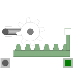 Model Modelica.Mechanics.Rotational.Components.IdealGearR2T
This is an ideal mass- and inertialess gearbox which transforms a 1D-rotational into a 1D-translational motion. If elasticity, damping or backlash has to be considered, this ideal gearbox has to be connected with corresponding elements. This component defines the kinematic constraint:
(flangeR.phi - internalSupportR.phi) = ratio*(flangeT.s - internalSupportT.s);
Extends from Modelica.Mechanics.Rotational.Interfaces.PartialElementaryRotationalToTranslational (Partial model to transform rotational into translational motion).
| Type | Name | Default | Description |
|---|---|---|---|
Boolean | useSupportR | false | = true, if rotational support flange enabled, otherwise implicitly grounded |
Boolean | useSupportT | false | = true, if translational support flange enabled, otherwise implicitly grounded |
Real | ratio | Transmission ratio (flange_a.phi/flange_b.s) |
| Type | Name | Description |
|---|---|---|
Flange_a | flangeR | Flange of rotational shaft |
Flange_b | flangeT | Flange of translational rod |
Support | supportR | Rotational support/housing of component |
Support | supportT | Translational support/housing of component |
 Model Modelica.Mechanics.Rotational.Components.IdealRollingWheel
A simple kinematic model of a rolling wheel which has no inertia and no rolling resistance. This component defines the kinematic constraint:
(flangeR.phi - internalSupportR.phi)*wheelRadius = (flangeT.s - internalSupportT.s);
Extends from Modelica.Mechanics.Rotational.Interfaces.PartialElementaryRotationalToTranslational (Partial model to transform rotational into translational motion).
| Type | Name | Default | Description |
|---|---|---|---|
Boolean | useSupportR | false | = true, if rotational support flange enabled, otherwise implicitly grounded |
Boolean | useSupportT | false | = true, if translational support flange enabled, otherwise implicitly grounded |
Distance | radius | Wheel radius |
| Type | Name | Description |
|---|---|---|
Flange_a | flangeR | Flange of rotational shaft |
Flange_b | flangeT | Flange of translational rod |
Support | supportR | Rotational support/housing of component |
Support | supportT | Translational support/housing of component |
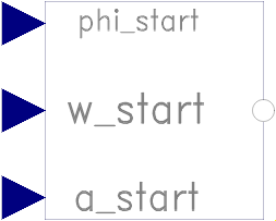 Model Modelica.Mechanics.Rotational.Components.InitializeFlange
This component is used to optionally initialize the angle, speed, and/or angular acceleration of the flange to which this component is connected. Via parameters use_phi_start, use_w_start, use_a_start the corresponding input signals phi_start, w_start, a_start are conditionally activated. If an input is activated, the corresponding flange property is initialized with the input value at start time.
For example, if "use_phi_start = true", then flange.phi is initialized with the value of the input signal "phi_start" at the start time.
Additionally, it is optionally possible to define the "StateSelect" attribute of the flange angle and the flange speed via parameter "stateSelection".
This component is especially useful when the initial values of a flange shall be set according to reference signals of a controller that are provided via a signal bus.
Extends from Modelica.Blocks.Icons.Block (Basic graphical layout of input/output block).
| Type | Name | Default | Description |
|---|---|---|---|
Boolean | use_phi_start | true | = true, if initial angle is defined by input phi_start, otherwise not initialized |
Boolean | use_w_start | true | = true, if initial speed is defined by input w_start, otherwise not initialized |
Boolean | use_a_start | true | = true, if initial angular acceleration is defined by input a_start, otherwise not initialized |
StateSelect | stateSelect | StateSelect.default | Priority to use flange angle and speed as states |
| Type | Name | Description |
|---|---|---|
input RealInput | phi_start | Initial angle of flange |
input RealInput | w_start | Initial speed of flange |
input RealInput | a_start | Initial angular acceleration of flange |
Flange_b | flange | Flange that is initialized |
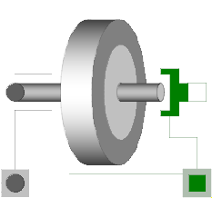
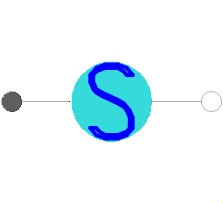 Model Modelica.Mechanics.Rotational.Components.RelativeStates
Usually, the absolute angle and the absolute angular velocity of Modelica.Mechanics.Rotational.Components.Inertia models are used as state variables. In some circumstances, relative quantities are better suited, e.g., because it may be easier to supply initial values. In such cases, model RelativeStates allows the definition of state variables in the following way:
An example is given in the next figure
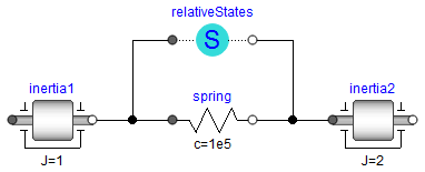
Here, the relative angle and the relative angular velocity between the two inertias are used as state variables. Additionally, the simulator selects either the absolute angle and absolute angular velocity of model inertia1 or of model inertia2 as state variables.
See also the discussion State Selection in the User's Guide of the Rotational library.
Extends from Modelica.Mechanics.Rotational.Interfaces.PartialTwoFlanges (Partial model for a component with two rotational 1-dim. shaft flanges).
| Type | Name | Default | Description |
|---|---|---|---|
StateSelect | stateSelect | StateSelect.prefer | Priority to use the relative angle and relative speed as states |
Angle | phi_nominal | 1 | Nominal value of the relative angle (used for scaling) |
| Type | Name | Description |
|---|---|---|
Flange_a | flange_a | Flange of left shaft |
Flange_b | flange_b | Flange of right shaft |
 Model Modelica.Mechanics.Rotational.Components.AngleToTorqueAdaptor
Adaptor between a flange connector and a signal representation of the flange. This component is used to provide a pure signal interface around a Rotational model and export this model in form of an input/output block, especially as FMU (Functional Mock-up Unit). Examples of the usage of this adaptor are provided in Rotational.Examples.GenerationOfFMUs. This adaptor has angle, angular velocity and angular acceleration as input signals and torque as output signal. Note, the input signals must be consistent to each other (w=der(phi), a=der(w)).
| Type | Name | Default | Description |
|---|---|---|---|
Boolean | use_w | true | = true, enable the input connector w (angular velocity) |
Boolean | use_a | true | = true, enable the input connector a (angular acceleration) |
| Type | Name | Description |
|---|---|---|
Flange_b | flange | |
input RealInput | phi | Angle to drive the flange |
input RealInput | w | Speed to drive the flange (w=der(phi) required) |
input RealInput | a | Angular acceleration to drive the flange (a = der(w) required) |
output RealOutput | tau | Torque needed to drive the flange according to phi, w, a |
 Model Modelica.Mechanics.Rotational.Components.TorqueToAngleAdaptor
Adaptor between a flange connector and a signal representation of the flange. This component is used to provide a pure signal interface around a Rotational model and export this model in form of an input/output block, especially as FMU (Functional Mock-up Unit). Examples of the usage of this adaptor are provided in Rotational.Examples.GenerationOfFMUs. This adaptor has torque as input and angle, angular velocity and angular acceleration as output signals.
| Type | Name | Default | Description |
|---|---|---|---|
Boolean | use_w | true | = true, enable the output connector w (angular velocity) |
Boolean | use_a | true | = true, enable the output connector a (angular acceleration) |
| Type | Name | Description |
|---|---|---|
Flange_a | flange | |
output RealOutput | phi | Flange moves with angle phi due to torque tau |
output RealOutput | w | Flange moves with speed w due to torque tau |
output RealOutput | a | Flange moves with angular acceleration a due to torque tau |
input RealInput | tau | Torque to drive the flange |
 Model Modelica.Mechanics.Rotational.Components.GeneralAngleToTorqueAdaptor
Adaptor between a flange connector and a signal representation of the flange. This component is used to provide a pure signal interface around a Rotational model and export this model in form of an input/output block, especially as FMU (Functional Mock-up Unit). This adaptor has angle, angular velocity and angular acceleration as input signals and torque as output signal.
Note, the input signals must be consistent to each other (w=der(phi), a=der(w)).
Extends from Modelica.Blocks.Interfaces.Adaptors.PotentialToFlowAdaptor (Signal adaptor for a connector with potential, 1st derivative of potential, and 2nd derivative of potential as inputs and
flow, 1st derivative of flow, and 2nd derivative of flow as outputs (especially useful for FMUs)).
| Type | Name | Default | Description |
|---|---|---|---|
Boolean | use_pder | true | Use input for 1st derivative of potential |
Boolean | use_pder2 | true | Use input for 2nd derivative of potential (only if 1st derivate is used, too) |
final Boolean | use_fder | false | Use output for 1st derivative of flow |
final Boolean | use_fder2 | false | Use output for 2nd derivative of flow (only if 1st derivate is used, too) |
| Type | Name | Description |
|---|---|---|
input RealInput | p | Input for potential |
input RealInput | pder | Optional input for der(potential) |
input RealInput | pder2 | Optional input for der2(potential) |
output RealOutput | f | Output for flow |
output RealOutput | fder | Optional output for der(flow) |
output RealOutput | fder2 | Optional output for der2(flow) |
Flange_b | flange |
 Model Modelica.Mechanics.Rotational.Components.GeneralTorqueToAngleAdaptor
Adaptor between a flange connector and a signal representation of the flange. This component is used to provide a pure signal interface around a Rotational model and export this model in form of an input/output block, especially as FMU (Functional Mock-up Unit). This adaptor has torque as input and angle, angular velocity and angular acceleration as output signals.
Extends from Modelica.Blocks.Interfaces.Adaptors.FlowToPotentialAdaptor (Signal adaptor for a connector with flow, 1st derivative of flow, and 2nd derivative of flow as inputs and
potential, 1st derivative of potential, and 2nd derivative of potential as outputs (especially useful for FMUs)).
| Type | Name | Default | Description |
|---|---|---|---|
Boolean | use_pder | true | Use output for 1st derivative of potential |
Boolean | use_pder2 | true | Use output for 2nd derivative of potential (only if 1st derivate is used, too) |
final Boolean | use_fder | false | Use input for 1st derivative of flow |
final Boolean | use_fder2 | false | Use input for 2nd derivative of flow (only if 1st derivate is used, too) |
| Type | Name | Description |
|---|---|---|
output RealOutput | p | Output for potential |
output RealOutput | pder | Optional output for der(potential) |
output RealOutput | pder2 | Optional output for der2(potential) |
input RealInput | f | Input for flow |
input RealInput | fder | Optional input for der(flow) |
input RealInput | fder2 | Optional input for der2(flow) |
Flange_a | flange |