 Package Modelica.Magnetic.FluxTubes.Examples.MovingCoilActuator.Components
Components to be used in examples
Package Modelica.Magnetic.FluxTubes.Examples.MovingCoilActuator.Components
Standard package icon.
Extends from Modelica.Icons.Package (Icon for standard packages).
| Name | Description |
|---|---|
ConstantActuator | Simple behavioural actuator model for system simulation |
PermeanceActuator | Detailed actuator model for rough magnetic design of actuator and system simulation |
 Model Modelica.Magnetic.FluxTubes.Examples.MovingCoilActuator.Components.PermeanceActuator
In the ConstantActuator model the force F is strictly proportional to the current i as indicated by the converter constant c. However, there is an additional non-linear force component in such an actuator that is due to the dependency of the coil inductance L on the armature position x. The inductance increases as the armature moves into the stator. The total force is
        1  2 dL
    F = - i  --  + c i
        2    dx
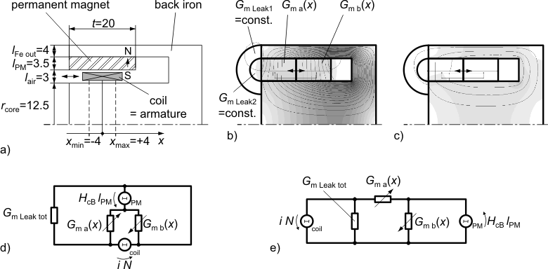
Both force components are properly considered with a simple permeance model as shown in the figures below. Figure (a) illustrates the dimensions of the axis-symmetric moving coil actuator that are needed in the permeance model. Figure (b) shows partitioning into flux tubes and the permanent magnetic field without current. G_ma and G_mb both are the permeances resulting from a series connection of the permanent magnet and air gap sections. The field plot of the coil-imposed mmf is shown in figure (c) without the permanent magnetic mmf (H_cB=0). The placement of the magnetic network components in figure (d) retains the geometric structure of the actuator. In figure (e), the permeance model is restructured and thus simplified.
| Type | Name | Default | Description |
|---|---|---|---|
Real | N | 140 | Number of turns |
Resistance | R | 2.86 | Coil resistance |
Radius | r_core | 0.0125 | Radius of ferromagnetic stator core |
Length | l_PM | 0.0035 | Radial thickness of permanent magnet ring |
Length | t | 0.02 | Axial length of permanent magnet ring and air gap respectively |
Length | l_air | 0.003 | Total radial length of armature air gap |
Length | l_FeOut | 0.004 | Radial thickness of outer back iron (for estimation of leakage permeance) |
BaseData | material | Material.HardMagnetic.BaseData() | Ferromagnetic material characteristics |
Mass | m_a | 0.012 | Mass of armature |
TranslationalSpringConstant | c | 1e+11 | Spring stiffness between impact partners |
TranslationalDampingConstant | d | 400 | Damping coefficient between impact partners |
Position | x_min | -0.004 | Position of stopper at minimum armature position |
Position | x_max | 0.004 | Position of stopper at maximum armature position |
| Type | Name | Description |
|---|---|---|
PositivePin | p | Electrical connector |
NegativePin | n | Electrical connector |
Flange_b | flange | Flange of component |
 Model Modelica.Magnetic.FluxTubes.Examples.MovingCoilActuator.Components.ConstantActuator
Similar to rotational DC-Motors, the electro-mechanical energy conversion of translatory electrodynamic actuators and generators of moving coil and moving magnet type can be described with the following two converter equations:
      F = c * i
    V_i = c * v
with electrodynamic or Lorentz force F, converter constant c, current i, induced back-emf V_i and armature velocity v. The model is very similar to the well-known behavioural model of a rotational one-phase DC-Machine, except that it is for translatory motion. For a moving coil actuator with a coil inside an air gap with flux density B and a total wire length l inside the magnetic field, the converter constant becomes
c = B * l.
The converter constant c as well as coil resistance R and inductance L are assumed to be known, e.g., from measurements or catalogue data. Hence this model is well-suited for system simulation together with neighbouring subsystems, but not for actuator design, where the motor constant is to be found on base of the magnetic circuit's geometry, material properties and winding data. See PermeanceActuator for a more accurate model of this actuator that is based on a magnetic network. Due to identical connectors, both models can be used in system simulation, e.g. to simulate a stroke as demonstrated in ArmatureStroke.
| Type | Name | Default | Description |
|---|---|---|---|
ElectricalForceConstant | k | 3.88 | Converter constant |
Resistance | R | 2.86 | Coil resistance |
Inductance | L | 0.0051 | Coil inductance at mid-stroke |
Mass | m_a | 0.012 | Armature mass |
TranslationalSpringConstant | c | 1e+11 | Spring stiffness between impact partners |
TranslationalDampingConstant | d | 400 | Damping coefficient between impact partners |
Position | x_min | -0.004 | Minimum armature position |
Position | x_max | 0.004 | Maximum armature position |
| Type | Name | Description |
|---|---|---|
PositivePin | p | Electrical connector |
NegativePin | n | Electrical connector |
Flange_b | flange | Flange of component |