Designate Surfaces as Gates
Identify any gates you've already designed in a CAD tool.
-
On the the Gate icon, click Designate
Surfaces as Gates.

-
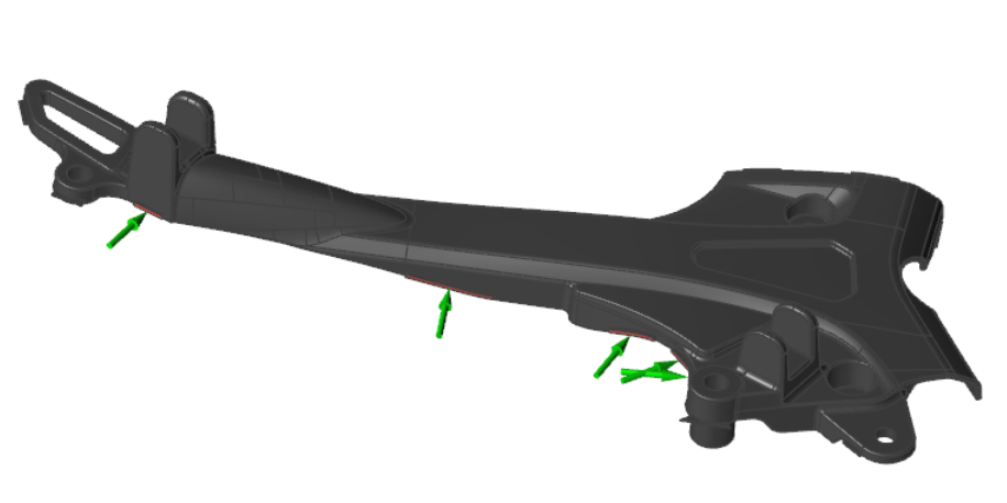
Click the predesigned gates.
Selected gates are designated with a green arrow.
Microdialog Options
Define the position, shape, and dimensions of the gate.
| Option | Description | |
|---|---|---|
| Move |
 |
Click to define the position and angle of the
gate. |
| Shape |
 |
Select a Circular or
Rectangular gate. Note: This option is only available when
adding virtual gates.
|
| Dimensions |
 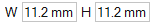 |
Note: This option is only available when
adding virtual gates.
|
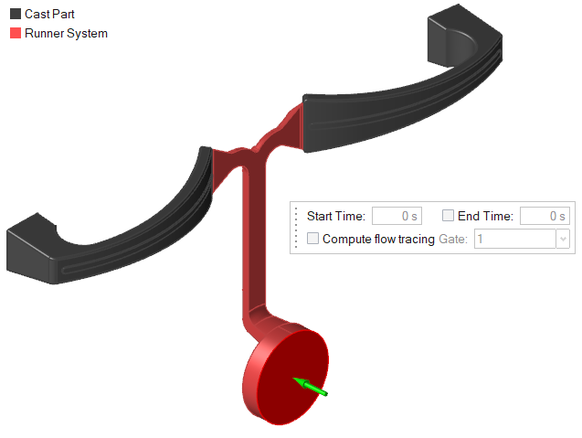
| Start Time | 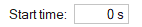 |
Enter the start time for this gate in seconds from the start of the
process. Note:
|
| End Time |  |
Enter the end time for this gate in seconds from the start of the process. Note:
|
| Compute Flow Tracing |  |
Enable this option to track the material flowing from each gate in an analysis. The flow tracing data appears in the Tracer ID result type. |
| Gate menu | 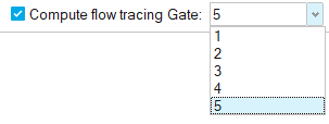 |
Use this menu to order the gates in your model. The numbers assigned
to the gates correspond to the colors in the Tracer ID result type. Note: For optimal clarity in the Tracer ID
result type, gates should be numbered sequentially.
|