To configure the ADC, it’s a good idea to first insert an F28x Config block in your diagram and set the CPU to your device. The ADC Config Properties dialog box for the device.
Note: The ADC Config dialog box is dependent on the target you select. If you selected a newer device, the dialog box parameters are different from the ones shown below.
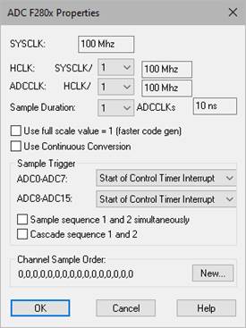
ADCCLK: Specifies the analog-to-digital converter clock.
Sample Duration: Chooses the number of ADC clock ticks for a given ADC sample. High impedance inputs require longer samples. A recommended duration is 20 nsec.
HCLK: Specifies the high-speed clock.
Sample Duration: Chooses the number of ADC clock ticks for a given ADC sample. High impedance inputs require longer samples. A recommended duration is 20 nsec.
Controls when to start sampling channels.
Cascade Sequence 1 and
2: Scans sequence 1 followed by sequence
2.
Sample Sequence 1 and 2 at the same time: Allows the simultaneous
sampling of the two sequences.
SYSCLK: Indicates the speed of the CPU clock
Use Continuous Conversion: Enables the continuous conversion option in the hardware.
Use Full Scale Value = 1: Provides direct read of the ADC result register with no scaling. When activated, the value will range between zero and 0.00007. When de-activated, Embed adds code to scale the result from zero to three.