Flow from Geometry - Elements

Figure 1.
You can load geometry from a CAD program into the graphical user interface and use it to create the flow model. The geometry is also useful for visualizing what the chambers and elements represent in the flow model. Use the function to read geometry in IGES or STEP format.
You can create an element directly from the geometry if Flow Simulator can recognize the surface geometry topology. Flow Simulator can recognize cylindrically shaped surfaces that are either full (360°) or partial (for example, 180°) circles. The automatic element creation is most useful for piping networks that use tube and bend elements.
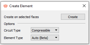
Create Element Details

Figure 2.
- Select the element type to create.
- From the Circuit Type drop-down menu, select
Compressible or
Incompressible.
- Compressible
- Create elements from the Compressible Gas Elements section of the Element Library.
- Incompressible
- Create elements from the Incompressible Liquid Elements section of the Element Library.
- Select the element type.

Figure 3.- Auto
- Automatically determines the element type to create, based on the surface topology.
- Tube
- Creates a tube element.
- Bend
- Creates a bend element.
- Orifice
- Creates an orifice element.
- From the Circuit Type drop-down menu, select
Compressible or
Incompressible.
- After your selections are complete, click
Create.
The CAD geometry changes color to indicate the surface(s) are ready to be selected.
- Select the surface(s) to use to create the elements.
- To end selection mode, close the window or click
Create again.
The newly created elements may have some of the geometric information populated during the creation process. Please inspect this information since not all surface topology is accurately measured during element creation.