ACU-T: 2000 Turbulent Flow in a Mixing Elbow
Prerequisites
Prior to starting this tutorial, you should have already run through the introductory tutorial, ACU-T: 1000 Basic Flow Set Up. To run this simulation, you will need access to a licensed version of HyperWorks CFD and AcuSolve.
Problem Description
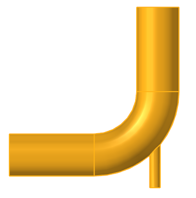
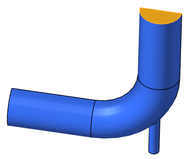
The problem characteristics shown here determine if the flow is laminar or turbulent by calculating the Reynolds number in the pipe. The diameter of the large inlet is 0.1 m, and the inlet velocity (v) is 0.4 m/s. The diameter of the small inlet is 0.025 m, and the inlet velocity is 1.2 m/s.

Figure 1. Schematic of Mixing Elbow
The fluid in this problem is water with the following properties that do not change with temperature: a density (ρ) of 1000 kg/m3 and a molecular viscosity (μ) of 1 X 10⁻³ kg/m-sec.
This value is useful in determining the Reynolds number, which in turn can be used to determine if the flow should be modeled as turbulent, or if it should be modeled as laminar.
where ρ is the fluid density, V is the fluid velocity, D is the diameter of the flow region, and μ is the molecular viscosity of the fluid. When the Reynolds number is above 4,000, it is generally accepted that flow should be modeled as turbulent.
The Reynolds numbers of 40,000 at the large inlet, 30,000 at the small inlet, and 47,500 for the combined flow indicate that the flow is turbulent throughout the flow domain. The simulation will be set up to model steady state, turbulent flow.
Start HyperWorks CFD and Open the HyperMesh Database
Validate the Geometry
Set Up the Problem
Set Up the Simulation Parameters and Solver Settings
Assign Material Properties
Assign Flow Boundary Conditions
Set Boundary Conditions for the Large Inlet
Set Boundary Conditions for the Small Inlet
Set Boundary Conditions for the Outlet
Set Boundary Conditions for the Symmetry Plane
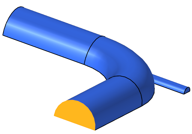
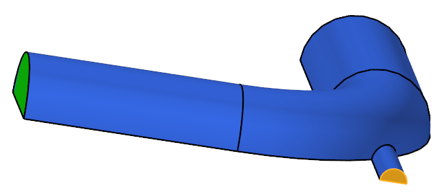
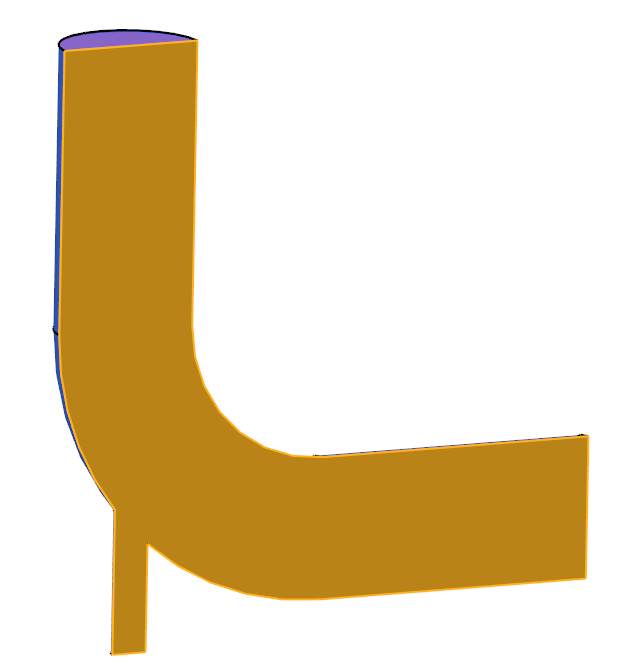
This geometry is symmetric about the XY midplane, and can therefore be modeled with half of the geometry. In order to take advantage of this, the midplane needs to be identified as a symmetry plane. The symmetry boundary condition enforces constraints such that the flow field from one side of the plane is a mirror image of that on the other side.
Generate the Mesh
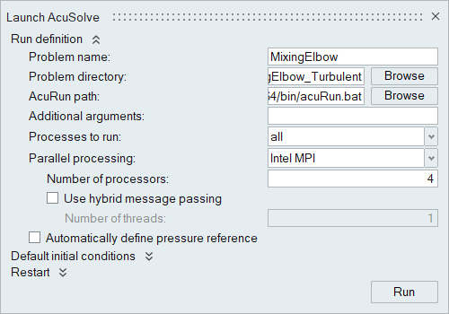
Run AcuSolve
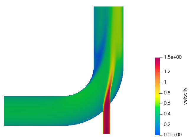
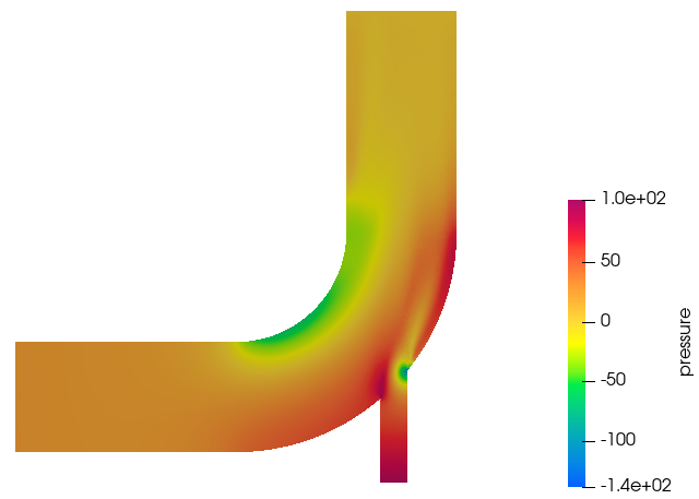
Post-Process the Results with HW-CFD Post
Summary
In this tutorial, you worked through a basic workflow to set up a CFD model, carry out a CFD simulation, and post-process the results. You started by importing the model in HyperWorks CFD. Then, you defined the simulation parameters and launched AcuSolve directly from within HyperWorks CFD. Upon completion of the solution by AcuSolve, you used the Post ribbon to create contour plots.


