What's New
View new features for MotionView 2022.1.
Altair Multi Body Solutions 2022.1 Release Notes
Highlights
- Flexbody Contact
- Entity Editor
- New Run Workflow
- Support for GPSTRESS
- Limited Multi-Threading
- CVT for Scooters
- Aerodynamics for Two-wheelers
- Slalom Events
- Tire Soft-Soil Obstacles
- Altair Driver Steering Control Using Torque
More details about these features, additional enhancements, and resolved issues are described below.
New Features
- Flexbody Contact
- MotionSolve supports 2D or 3D contact force between two bodies. In
previous releases, MotionSolve only supported contact for rigid bodies.
With this release, contact has been extended to CMS-based flexible
bodies. Whenever any rigid or flexible geometry on the first body
penetrates any rigid or flexible geometry on the second body, contact
normal and frictional forces are generated. The normal force tends to
repulse motion along the common normal at the contact point. The
frictional force tends to oppose relative sliding velocity at the
contact point. The contact force vanishes when the geometries no longer
intersect. New processes have been defined to account for flexbody deformation involving loads generated from general part-to-part contact or loads occurring around joint region. Those processes have been integrated into the flexible preparation tool FlexPrep.
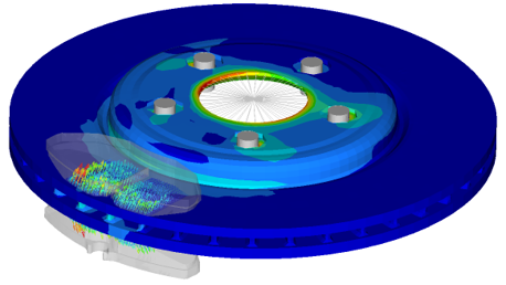 Figure 1.
 - Entity Editor
- MotionView’s new interface comes with an Entity Editor that lists the
entity properties to edit. In addition to what was available in 2022,
for 2022.1, the following entities now have an editor:
- Points, Bodies, Rigid Group, Markers, and Graphics
- Joints, Bushings, Spring Dampers, and Forces
- Couplers, Gears, Advanced Joints, and Contacts
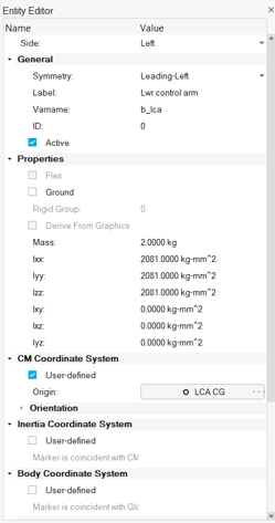 Figure 2.
 - New Run Workflow
- The new MotionView interface has an improved workflow for solving the
model through MotionSolve. The solution is carried through a live
connection to the solver through its msolve Python APIs. The new
workflow offers:
- Animation of the solution live as it progresses.
- Run status progress bar.
- Run history – Lists all runs submitted through the live process.
- Load results in HyperView and HyperGraph for detailed post-processing.
From the Analyze ribbon, select the Run tool.
- Support for GPSTRESS
- If the system contains a flexible body made of shell or solid elements,
the stresses of that body are usually evaluated by either printing or
contour plotting the element component stresses. However, element
stresses are calculated at the center and vertices of the elements. This
might not always be sufficient in cases where more accurate stress
values at the grid points are required. The grid point stress (GPSTRESS)
option in Altair OptiStruct offers you an alternative. GPSTRESS
calculates the stresses at the grid points from the adjoining shell and
solid elements.
For CMS based flexible bodies, MotionSolve supports the calculation of stresses on the grid points if the FlexH3D file contains grid point stress mode shapes. Grid point stresses must be explicitly requested in OptiStruct during the CMS analysis. The grid point stresses can be requested in the H3DOutput command statement (solver only). This option will be soon added to MotionView.
- Limited Multi-Threading
- The dynamic simulation in MotionSolve accounts for all the accelerations
(linear, angular, centrifugal, and Coriolis), forces, and constraints.
In other words, it solves the equations of motion in their most general
form, including nonlinear effects. This enables you to develop accurate
system level simulations of complex mechanical systems. At the core of most analyses, MotionSolve is solving a set of linear equations (A x = b). By default, a direct LU solver is utilized that is very robust and fast, but modest for parallel computation. Tests showed that most multi body models in MotionSolve perform best if up to four parallel threads are assigned. However, some models might benefit from more threads. By default, MotionSolve is now limited to four threads (nt=4), but the limit can be increased using the “nt” option.Note: A larger number for "nt" checks out more Altair Units for a single MotionSolve run. Please refer to the Altair Units Licensing documentation for more information on the solver unit draw.
- CVT for Scooters
- The Two-Wheeler Library in MotionView includes a CVT (Continuously
Variable Transmission) Powertrain for Scooter models. The Altair CVT
Powertrain is a mathematical formulation that represents an automobile
IC engine powertrain with CVT in the form of Control State Equations
(CSE).
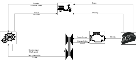 Figure 3. The CVT Powertrain can be included in the Full Scooter with Driver assembly model under the Two-wheeler assembly wizard library. With the possibility to design and control the parameters of the CVT Powertrain, this feature expands the capability of scooters modeling in MotionView, enabling a wide range of design evaluations and vehicle performance simulations.
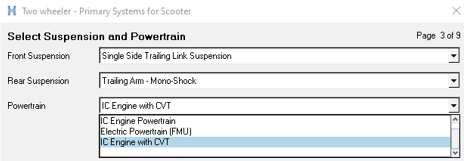 Figure 4.
 - Aerodynamics for Two-wheelers
- MotionView adds the option to include Aerodynamic Forces in motorcycle
and scooter models. The option is available in the Two-wheeler assembly
wizard library.
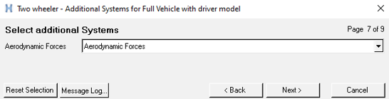 Figure 5.
 The aerodynamic parameters are entered in a Teim Orbit property file, *.aae, including environment parameter, wind velocity, side forces, drag, lift, yaw, and roll coefficients.
- Slalom Event
- MotionView contains an event to evaluate the performance of vehicles in
a slalom maneuver. The Slalom Event drives the vehicle in a sequence of
turns around cones in alternate directions measuring the vehicle state
variables, tire forces, suspension behavior, and other performance
indicators.
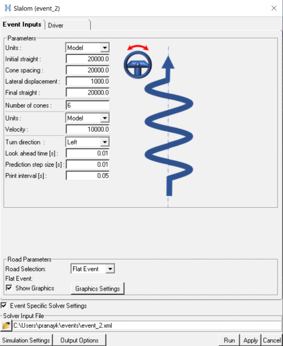 Figure 6.
 The Slalom Event is available for two-wheeler, car, and truck models using the Altair Driver. An automated Report template is available to simplify the post-processing of the simulation event containing the main output result plots.
- Tire Soft Soil Obstacles
- In the previous release, MotionView/MotionSolve included a new empirical
tire model for soft soil interaction to study the dynamic behavior of
vehicles traversing a compressible surface. The soil surface was
essentially flat, and an additional graphic was implemented to visualize
the tire sinking into the soft ground in the post-processing using
HyperView.
In this release, MotionView/MotionSolve enables the addition of obstacles to represent the compressible surface. A total of nine different obstacles can be included in the road property file: Rectangular, Circular, Bump, Ramp, Roof, Sine, Sine-sweep, Plank obstacle, and Crown obstacle.
The obstacles can be represented as soft soil with the same or a different surface material, or as a rigid obstacle.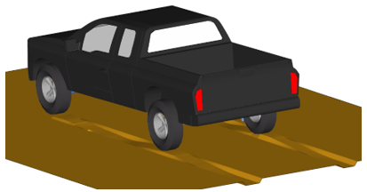 Figure 7. Note: The graphic used to visualize the soft-soil road can capture the obstacle's information only when the tire reaches its location. Rigid obstacles cannot be visualized in the post-processing graphic. This is a known issue that will be fixed in a future release.
 - Altair Driver Steering Control Using Torque
- In vehicles using leaning control (two-wheelers and three-wheelers), it
is now possible to perform the steering control using motion or torque.
The steering control using torque enables a smooth response of the
system. The selection of the steering control type is done in the Event
Editor under the Driver properties tab; the default selection is set the
Motion.
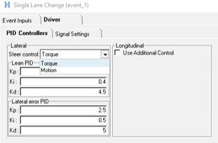 Figure 8. Note: The Steer Angle and Torque output request available in the Front suspension system of the Library models reports zero torque when the Steer Control type is set to Torque. For plotting steer torque in this case, it is advised to select: Driver outputs: Steer Torque – F2. This is a known limitation and will be resolved in a future release.
Enhancements
- Parameterize Existing Points with Respect to a Marker
- A new tool is available in the HyperWorks interface to define existing points relative to a marker. Using this option, independent points can be parametrized with regard to a marker, so that changing the marker’s position or orientation would also move the points. Right-click the context menu on selected point to display the tool.
- Parametrizing a Point to a Node
- A new location function, getnodecoordinates, can be used to parametrically link a point’s location to a node in the model. The node can belong to a flexible body or a graphic of type File Graphic. This function causes repositioning of such a point when the flexible body or the graphic is moved. When a point is created at a node (using Alt+Click) through the Point creation tool, the point coordinates are set using the getnodecoordinates function.
- Automatic Parsing of Windows Path into a Unix-equivalent Path
- A new environment variable, DOS_DRIVE_$, assigns a Windows drive letter to Unix paths. This creates a Windows-style path, starting with the drive letter, on Unix/ Linux. MotionSolve, while parsing any path, replaces the drive letter and colon ($:) with the content of the respective environment variable. This facilitates using input files (XML, PY) with references to other files (for example, H3D) containing Windows drive letters in Unix.
- Update to ProximitySensor
- The ProximitySensor element measures the minimum distance between the graphics or a mesh of two bodies. The sensor tracks the state of interference of the graphics and/or mesh, the length of the minimum distance, and the coordinates of a pair of closest points. In this release, ProximitySensor has been extended to flexible bodies.
- Updates to PTCV and PTSF
- The point-to-curve and point-to-surface constraints have been extended to support perpendicular constraint.
- Active State Python
- MotionView and MotionSolve support Python as a scripting language. Active State Python has been upgraded to version 3.8.10.
- Vehicle Control FMU Blocks Showing Only Relevant Parameters
- The FMU control blocks used in the vehicle dynamic simulations (EPAS,
TC, ABS, ESP, and Electrical Powertrain) were enhanced to expose only
the meaningful design parameters of the control unit. This facilitates
the understanding and the design modeling of the controls in the
MotionView environment.
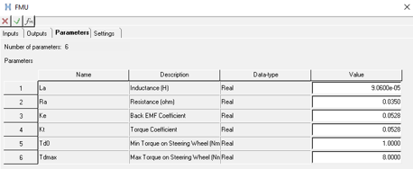 Figure 9.
 - New tutorial explaining how to add the Altair Driver in a generic model
- A tutorial is available in the Altair Simulation online help that explains how to include the Altair Driver control unit in a generic model created with simple entities and not using the Assembly Wizard library. The tutorial also demonstrates how to include a Slalom Event and add external control signals to the model.
Resolved Issues
- Definition-based entities fail to create using the Python API when path separator ‘\\’ is used.
- Contact model takes longer to export than previous versions.
- Spring graphics appear skewed when one end point has all coordinates with uniform scaling.
- The 'Create points at interface nodes' macro in the flexbody Nodes dialog does not work correctly when executed a second time.
- Graphics System collector does not allow picking using the Advanced selection dialog.
- “Show Spring” option on the Spring entity is not correctly exported to MotionSolve PY.
- An application error is encountered in the Data Summary's Spring Damper tab.
- Move tool – Snapping to mesh nodes using Alt key does not work.
- Move tool – Fails in the first attempt to grab the geometrical objects for move.
- Display of Compliant Joint is not proper in Topology View.
- MotionView does not allow export of flexbody without interface nodes.
- Application error when attempting to ungroup a rigid group containing grounded bodies.
- Application error when changing the variable name in the Entity Editor.
- Inconsistent invariants between OptiStruct and MotionView XML writer can occur in the FlexH3D if there is a MODEL card in FEM that reduces the model information.
- Linear analysis: Fixed an issue with the C matrix when POUTPUT has a force expression that is referring to BEAM, BUSH, or FIELD.
- Velocity motion with initial displacement has issues during an analysis after a static step.
- The error calculation for the controller in the Altair Driver steering motion control was improved to provide a smoother output torque signal in the steering joint.
- Altair Driver does not abort simulations when the demand path/velocity are violated.
Known Issues
- Model Identification Tool 2022.1
- In HyperWorks v2022.1, the Fit Monitor that shows the progress of the fitting process is not displayed. Use View Jobs to check the fitting jobs’ status. This issue will be fixed in a future release.