Force: Contact
Model ElementForce_Contact defines a 2D or 3D contact force between two bodies.
Description
Force_Contact defines a 2D or 3D contact force between two bodies. Either rigid or flexible CMS bodies can be used. Rigid bodies are characterized by a set of one or more geometries, which can be a 3-D mesh, an analytically defined solid, or a 2D curve. Flexible bodies (CMS based only) are characterized by a Body_Flexible, which references an H3D file for the finite element mesh. Whenever any geometry on the first body penetrates any geometry on the second body, contact normal and frictional forces are generated. The normal force tends to repulse motion along the common normal at the contact point. The frictional force tends to oppose relative sliding velocity at the contact point. The contact force vanishes when the geometries no longer intersect.
Format
<Force_Contact
     id                             = "integer"
  [  label                          = "integer"   ]
  [  full_label                     = "string"    ]
 {
     num_i_graphics                 = "integer"
     i_graphics_id                  = "integer_list"
 |
     i_flexbody_id                  = "integer"
  [  i_flip_flex                    = { "TRUE" | "FALSE" } ]
 }
 {
     num_j_graphics                 = "integer"
     j_graphics_id                  = "integer_list"
 |
     j_flexbody_id                  = "integer"
  [  j_flip_flex                    = { "TRUE" | "FALSE" ]
 }
     ignore_penetration_larger_than = "real"
     master_surface                 = { "I" | "J" | "I_and_J" | "AUTO" }
     enable_node_mode               = {"AUTO" | "FALSE" }
     enable_analytical              = {"AUTO" | "FALSE" }
     contact_stability_2d           = "real"
{
     cnf_type                       = "POISSON"
     penalty                        = "real"
     restitution_coef               = "real"
     normal_trans_vel               = "real"
     |
     cnf_type                       = "IMPACT"
     stiffness                      = "real"
     exponent                       = "real"
     damping                        = "real"
     dmax                           = "real"
     |
     cnf_type                       = "VOLUME"
     i_elastic_modulus              = "real"
     j_elastic_modulus              = "real"
     i_layer_depth                  = "real"
     j_layer_depth                  = "real"
     exponent                       = "real"
     damping                        = "real"
     |
     cnf_type                       = "USERCNF"
     cnf_param_string               = "USER( [[par_1 [,...][,par_n]] )"
     cnf_fnc_name                   = "string"
   { cnf_dll_name                   = "string"
    |
     script_name                    = "string"
     interpreter                    = { "PYTHON" | "MATLAB" }
   }
}
{
     cff_type                       = "COULOMB_ON"
     mu_static                      = "real"
     mu_dynamic                     = "real"
     stiction_trans_vel             = "real"
     friction_trans_vel             = "real"
     |
     cff_type                       = "COULOMB_DYNAMICONLY"
     mu_dynamic                     = "real"
     friction_trans_vel             = "real"
    |
     cff_type                       = "COULOMB_OFF"
    |
     cff_type                       = "USERCFF"
     cff_param_string               = "USER( [[par_1 [,...][,par_n]] )"
     cff_fnc_name                   = "string"
   { cff_dll_name                   = "string"
    |
     script_name                    = "string"
     interpreter                    = { "PYTHON" | "MATLAB" }
   }
}
{
     cpost_param_string             = "USER( [[par_1 [,...][,par_n]] )"
     cpost_fnc_name                 = "string"
   { cpost_dll_name                 = "string"
    |
     cpost_script_name              = "string"
     cpost_interpreter              = "PYTHON"
   }
}
Attributes
- id
- Element identification number (integer>0).
This number is unique among all Force_Contact elements and uniquely identifies the element.
Note: id is used only to identify the Force_Contact element to be modified. By itself, id cannot be modified. - label
- The name of the Force_Contact element. This argument is optional.
- full_label
- The full label of the Force_Contact element. This attribute is typically populated by MotionView as per the model hierarchy. This argument is optional.
- num_i_graphics
- If the first body is rigid, this argument specifies the number of
Post_Graphic elements on the first body that
are to be considered in evaluating the contact
force.
num_i_graphics > 0.
- i_graphics_id
- If the first body is rigid, this argument lists the
Post_Graphic element IDs on the first body to
be considered for contact. The number of IDs in this list is specified
by num_i_graphics.Note: All the Post_Graphic entities must belong to the same body.
- i_flexbody_id
- If first body is flexible, this argument specifies the ID of
Body_Flexiblefor the first body to be considered for contact. - i_flip_flex
- Reverses the direction of the surface normal on flexible body I. This
argument is optional. Choose from TRUE or
FALSE.The default is FALSE.
See Comment 10 for more details on usage.
- num_j_graphics
- If second body is rigid, this argument specifies the number of Post_Graphic elements on the second body that are to be considered in evaluating the contact force.
- j_graphics_id
- If second body is rigid, this argument lists the
Post_Graphic element IDs on the second body to
be considered for contact. The number of IDs in this list is specified
by num_j_graphics.Note: All the Post_Graphic entities must belong to the same body.
- j_flexbody_id
- If second body is flexible, this argument specifies the ID of Body_Flexible for the second body to be considered for contact.
- j_flip_flex
- Reverses the direction of the surface normal on flexible body J. This argument is optional. Choose from TRUE or FALSE.
- ignore_penetration_larger_than
- Use this attribute to change the maximum penetration depth that MotionView considers for evaluating contact forces. Any value above this threshold is ignored.
- master_surface
- Specifies which surface should be used as the master surface while
calculating the penetration depth, point of contact, contact normal,
and so on. Options include:
I: The surface of body I is used as the master surface.
J: The surface of body J is used as the master surface.
I_AND_J: Surfaces of both bodies, I and J, are used as master surface alternatively and the result is summed up.
AUTO: Let MotionView decide which geometry to use as the master surface. This is the default and recommended option.
- enable_node_mode
- For mesh based geometries, specifies whether the normal forces are calculated at the centers of the interconnected triangular elements (FALSE), or at their connection nodes (TRUE).
- enable_analytical
- Specifies whether MotionView should use an analytical description, where possible. Select TRUE or FALSE.
- contact_stability_2d
- Specifies a stability value that is used when calculating the contact point and penetration depth in 2D curve contact.
- cnf_type
- Specifies whether the POISSON, IMPACT, VOLUME or user defined (USERCNF) force model is to be used for calculating the contact normal force.
- penalty (POISSON)
- Specifies the stiffness parameter that is used to calculate the spring force. A large value for penalty permits only a small penetration between the two contacting geometries; a small value permits a larger penetration. Consider using a penalty value that is as small as possible, but still captures realistic deformation, to improve solver performance.
- restitution_coef (POISSON)
- Defines the coefficient of restitution (COR) between the geometries in contact. This is used in the computation of the contact force. A value of zero specifies perfectly plastic contact meaning that the two bodies coalesce after contact. A value of one specifies perfectly elastic contact. No energy is lost in the collision and the relative velocity of separation equals the relative velocity of approach.
- normal_trans_vel (POISSON)
- Defines the velocity limit between the two bodies at which full damping is applied in the contact force. If unset by the user, MotionView initializes it to 1.
- stiffness (IMPACT)
- The stiffness parameter of the contact; this is the same parameter as found for the IMPACT function. A large value for stiffness permits only a small penetration between the two contacting geometries; a small value permits a larger penetration. This parameter must be non-negative. Consider using a stiffness value that is as small as possible, but still captures accurate deformation, to improve solver performance.
- exponent (IMPACT)
- The exponent of the force deformation characteristic of the contact interface. For a stiffening spring characteristic, it must be greater than 1.0 and for a softening spring characteristic, it must be less than 1.0.
- damping (IMPACT)
- The maximum damping coefficient. It must be non-negative.
- dmax (IMPACT)
- The penetration at which full damping is applied. It must be a positive number.
- i_elastic_modulus (VOLUME)
- Specifies the elastic modulus for the geometries belonging to body I for the Volume force model. The value of this elastic modulus can be derived from the Bulk and Shear Modulus of a material.
- j_elastic_modulus (VOLUME)
- Specifies the elastic modulus for the geometries belonging to body J for the Volume force model. The value of this elastic modulus can be derived from the Bulk and Shear Modulus of a material.
- i_layer_depth (VOLUME)
- Specifies the size of the layer depth for the geometries belonging to body I.
- j_layer_depth (VOLUME)
- Specifies the size of the layer depth for the geometries belonging to body J.
- exponent (VOLUME)
- The exponent of the force deformation characteristic of the contact interface. For a stiffening spring characteristic, it must be greater than 1.0 and for a softening spring characteristic, it must be less than 1.0.
- damping (VOLUME)
- The coefficient of damping used to calculate the damping force for the VOLUME force model
- cnf_param_string (USERCNF)
- Specify a list of parameters that are passed from the data file to the user written subroutine, CNFSUB.
- cnf_dll_name (USERCNF)
- Specifies the path and name of the shared library containing the contact force calculation subroutine. MotionSolve uses this information to load the user subroutine in the library at run time.
- cnf_fnc_name (USERCNF)
- Specifies an alternate name for the contact normal force subroutine, that is other than CNFSUB.
- script_name (USERCNF, USERCFF)
- Specifies the path and name of the user written script that contains the routine specified by cnf_fnc_name or cff_fnc_name.
- interpreter (USERCNF, USERCFF)
- Specifies the interpreted language that the user script is written in. Valid choices are MATLAB or PYTHON.
- cff_type
-
Specifies the friction force model that will be used to compute the contact friction force. Choose from "COULOMB_ON", "COULOMB_OFF", "DYNAMIC_ONLY" or "USERCFF".
cff_type = "COULOMB_ON" specifies that friction forces are to be calculated and applied at the contact location. MotionSolve uses the Coulomb model for friction force.
cff_type = "COULOMB_OFF" specifies that frictional forces are not calculated or applied at the contact location. Friction is turned off.
cff_type = "COULOMB_DYNAMICONLY" specifies that only the dynamic friction is active.
cff_type = "USERCFF" specifies that a user defined friction force model is to be used.
- mu_static
-
Defines the coefficient of static friction when the friction is in the static regime.
MotionSolve uses a step function to transition between the static and dynamic friction regimes.
- mu_dynamic
- Defines the coefficient of dynamic friction when the friction is in the
dynamic regime.
MotionSolve uses a step function to transition between the static and dynamic friction regimes. The coefficient of dynamic friction must be smaller than or equal to the coefficient of static friction.
- stiction_trans_vel
- The velocity at which the friction regime transitions to stiction.
- friction_trans_vel
- The velocity at which the friction regime transitions to friction.
- cff_dll_name (USERCFF)
- Specifies the path and name of the shared library containing the contact friction sub subroutine. MotionSolve uses this information to load the user subroutine in the library at run time.
- cff_fnc_name (USERCFF)
- Specifies an alternate name for the contact normal force subroutine. In other words, other than CFFSUB.
- cff_param_string (USERCFF)
- Specify a list of parameters that are passed from the data file to the user written subroutine, CFFSUB.
- cpost_dll_name
- Specifies the path and name of the shared library containing the contact post sub subroutine. MotionSolve uses this information to load the user subroutine in the library at run time.
- cpost_fnc_name
- Specifies an alternate name for the contact post subroutine. In other words, other than CONTACTPOST.
- cpost_param_string
- Specify a list of parameters that are passed from the data file to the user written subroutine, CONTACTPOST.
- cpost_interpreter
- Specifies the interpreted language that the user script is written in. Currently, only Python is supported as an interpreter for the CONTACTPOST subroutine.
- cpost_script_name
- Specifies the path and name of the user written script that contains the routine specified by cpost_fnc_name.
Modeling and Debugging Tips
- Confirm that models run without contact before adding them.
- Start modeling with contact friction off, and add it later after getting the normal force running.
- Some experimentation is usually required for tuning the contact parameters to get realistic and stable results.
- Small values for stiction_trans_vel and friction_trans_vel cause the integrator to take too small of steps when the coefficient of friction is large. Increase the value for stiction_trans_vel if you are experiencing integration difficulties. In our experience, this does not change the results significantly.
- Large values for the penalty or stiffness decreases the penetration allowed between geometries; however they also tend to decrease the integrator step size. Consider allowing as much penetration of the geometries as will still capture the behavior of the system that you're interested in measuring. This will be model-dependent. The contact force computation will be much smoother in general if a moderate amount of penetration (due to a lower stiffness/penalty) is allowed. Ask yourself, "Will 0.1 mm of penetration change the behavior of my system? Will 1 mm?"
- In general, a finer mesh at the contact surface will help obtain more accurate results. However, a fine mesh also increases the computational effort of the collision-detection algorithm, which may slow down the simulation.
- Check the normals of the geometries to make sure that they have been defined properly for the contact. In the Tria mesh geometry, the normal is defined by a right-hand rule of the mesh nodes. For example, you can view the normals using the check normals tool in the Contact panel in MotionView.
- If the contacts are not detected or pass through each other during the
simulation, try one of the following: decreasing the integrator step size
(for example, h_max), decreasing the error tolerance,
increasing the penalty/stiffness (if too soft), or checking the element
normals.
Alternatively, you can turn on the "zero crossing" action for the contact sensor in the Contact panel in MotionView. By doing this, MotionSolve will attempt to determine the moment of first contact more accurately which may alleviate this problem. For more information on this sensor, please refer to the documentation for Sensor_Event.
- If the integrator fails, use DebugOutput to determine if the contact is causing problems. If it is, then try one of the following: decreasing the contact penalty/stiffness and/or damping (if too large), decreasing h_max, increasing the integrator error tolerance, adding damping to other stiff entities in the model, or tuning the contact friction parameter as described previously.
Limitations
- Stiction or stick-slip phenomena are not supported at this time.
- For analytical Cylinder to Box contact, a contact between the Edge or Vertex of a Box to the flat side of the Cylinder is not supported at this time.
Example-1: Mesh-to-Mesh Contact
The image below demonstrates an epicyclic gear train that is used in a child's toy. When the child cranks the sun gear, the other gears rotate.
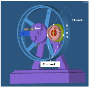
Figure 1. An Epicyclic Gear Train used in a Child's Toy
The Force_Contact statements for this example are shown below. The system is modeled in SI units.
<Force_Contact
    id                    = "1"
    num_i_graphics        = "1"
    i_graphics_id         = "82"
    num_j_graphics        = "1"
    j_graphics_id         = "92"
    cnf_type              = "POISSON
    penalty               = "1E6"
    restitution_coef      = "0.52"
    cff_type              = "COULOMB_ON"
    mu_static             = "0.08"
    mu_dynamic            = "0.05"
    stiction_trans_vel    = "0.005"
    friction_trans_vel    = "0.01"
/><Force_Contact
id = "2"
num_i_graphics = "1"
i_graphics_id = "93"
num_j_graphics = "1"
j_graphics_id = "73"
cnf_type = "POISSON"
penalty = "1E6"
restitution_coef = "0.52"
cff_type = "COULOMB_ON"
mu_static = "0.08"
mu_dynamic = "0.06"
stiction_trans_vel = "0.005"
friction_trans_vel = "0.0l"
/>For a more detailed example, see the tutorial MV-1010: Contact Simulation using MotionSolve.
Example-2: Analytical 3D Contact
This example illustrates the use of analytical 3D contact. There is no change to the user actions in MotionView. Behind the scenes, the solver recognizes the geometry pair in contact as being “simple” and it switches to using a specialized analytical contact formulation.
The model consists of a cylinder that is placed on a flat box. The cylinder rotates about its axis, which is parallel to the box top surface. A dynamic simulation is performed to evaluate the contact behavior for this simple case. The rotation of the cylinders simply causes triangles in the meshes to move in and out of contact. There is no change in the contact kinematics. Thus, one would expect the contact algorithm to report a constant force.
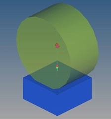
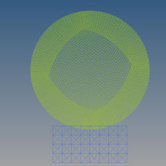 Figure 2. 3D analytical contact – cylinder rotating on a box
The problem is solved using 3D analytical contact as well as mesh-to-mesh contact. The contact forces are shown in the plot below.
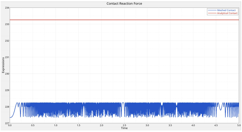
Figure 3. Contact forces at the box-cylinder interface – Analytical contact (Red) vs. Mesh-to-mesh contact (Blue)
The analytical contact reports a constant force as expected. The mesh-to-mesh contact representation, in contrast, reports a lower force. Moreover, as triangles move in and out of contact, in mesh-to-mesh contact, the force changes to reflect this. The variation in the force can be decreased by using finer tessellations, however this would increase the cost of the simulation.
The image below compares the performance of the analytical contact against the mesh-to-mesh contact. The analytical contact (left) is about 21x faster than the mesh-to-mesh contact (right) for this simple model.
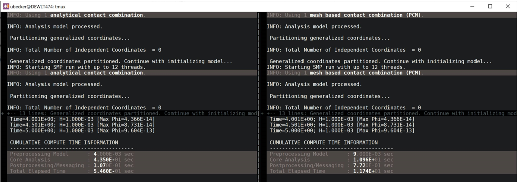
Figure 4. Analytical contact vs. Mesh-to-mesh contact – A performance comparison
Comments
- MotionView use a geometric representation of the
contacting bodies to compute the contact force. This geometrical
representation of the body is termed a graphic for that body. MotionView relies on a collision engine to detect intersection
or penetration between two graphics. Graphics can be 3D solid meshes for
rigid and flexible bodies, 3D analytical shapes for rigid bodies, and 2D
rigid curves.
Many geometric combinations are possible for 3D contact. When enable_analytical is set to “TRUE”, MotionView uses analytical representations for rigid bodies to compute accurate, fast, and smooth contact forces. When this is not possible, MotionView uses a general 3D mesh-to-mesh-contact.
Support for the different combinations is shown in the table below.

Figure 5. Table 1: Contact kinematics calculation methods for supported geometriesIn the above table, the entries in each cell have the following meaning:- Analytical
- Each of the contacting geometries is represented by an analytical expression. Contact between the geometries is determined analytically. Contact point locations and normal are computed without using any tessellation representations. Curved geometries are represented exactly.
- Semi
- One of the geometries is represented analytically. In other words, it is not tessellated. However, the other contacting geometry is tessellated and represented as a mesh. The accuracy is dependent on the accuracy of the tessellation.
- Mesh
- Both geometries are tessellated. A general mesh-to-mesh contact detection method is used. Contact accuracy is dependent on the accuracy of the mesh. The contact detection speed is inversely dependent on the mesh density. In other words, it will take more time to compute the contact kinematics between fine meshes.
Multiple graphics can be associated with a rigid body, but only a single graphic can be associated to a flexible body.
Using a 3D mesh representation: The graphics of a rigid body are required to be meshed using triangular elements. The graphic of a flexible body is directly adopted from its finite element mesh. A meshed graphic is a set of interconnected elements that describes a closed solid. This is illustrated in the figure below:
Figure 6. 3D representation of geometries using a mesh - Geometrical representation of two gear bodies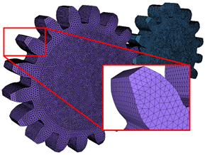
Figure 7. 3D representation of geometries using a mesh - Meshed representation of the same gear bodiesMotionSolve prescribes certain conditions for the meshed representation of a ridig body's graphic(s). These conditions must be met to generate realistic contact forces. These are:- Only triangular shell elements are allowed in the meshed representation. Quadrilateral or other shell elements are not permitted.
- The mesh must be a surface mesh. In other words, a mesh comprised of 2D triangular shell elements with no thickness. Solid meshes that make use of tetrahedral, hexahedral or other element types are not required.
- The mesh must enclose a volume; it must be closed. In other words, there must not be any free edges or cracks in the mesh. For example, a flat surface with zero volume is not allowed.
- T-connections are not allowed in the mesh - this means that an edge of a triangular element must be shared by no more than two elements.
- The surface normal for a meshed representation of a body’s graphic(s) must point outward from the surface that can come into contact. The normal direction must be defined in the corresponding graphic component (see Post: Graphic) .
For more information on these rules, please refer to Best Practices for Running 3D Contact Models in MotionSolve.
Graphics for rigid bodies may be defined in many ways:- For spherical geometries, MotionSolve can use an analytical
description of the geometry (based on a radius and a
location for the center of the sphere) while computing the
contact point, contact normal, and other quantities. This
approach is followed whenever MotionSolve detects a primitive
sphere geometry (of type =
"SPHERE" in Post_Graphic) for body
I, body J, or both. There are two advantages of using an
analytical description for a spherical body:
- Since there is no surface mesh, there are no errors due to the approximation of the surface by a triangulated mesh. This means the contact forces are more accurate;
- The solution time is typically much smaller for contact involving a sphere and a generalized 3D mesh.
To force MotionSolve to use a meshed representation of the sphere geometry, you can specify enable_sphere_to_mesh to be FALSE. This way, MotionSolve will mesh the primitive sphere geometry and use the meshed representation of the sphere to compute the contact related quantities.
- For simple shapes, you may use built-in primitive graphics provided by MotionSolve such as Sphere, Frustum, Box, and so on. For these primitive shapes, MotionSolve meshes the surface internally (using the attribute refinement_level in Post: Graphic) to determine the density of the mesh.
More complicated shapes can be defined in a CAD package and imported to MotionSolve using the Import CAD Tool in MotionView. Please see Import CAD or FE for more information on how CAD geometry can be meshed using this tool. Alternatively, you may also use HyperMesh to mesh your CAD graphics.
Using a 3D analytical representation: When the two contacting rigid geometries are “simple”, the general mesh-to-mesh contact method is not used. Simple geometries include sphere, box, cylinder and frustrum. In this case, simpler analytical computations are employed to detect the contact point locations and the directions of the normal. Tessellation of these geometries is not required, and it is not used.
Using a 2D representation: MotionSolve also supports contact between two curves that represent two rigid bodies. 2D curve graphics can be specified by referencing a Post_Graphic of type = "CURVE". Using 2D curve-based contact can be advantageous over 3D mesh-based contact when:- It is known a prior that the contact occurs only along the curves that are defined. Further, contact is expected to occur within the plane in which the two curves are defined. In other words, there are no out-of-plane contact forces that are expected.
- The curves between which the contact is to be calculated are smooth and represent the curvature of the 3D geometry well.
There may be several advantages of simulating rigid body contact using 2D curves over 3D tessellated geometry:- More accurate results: Results are more accurate since there is less error due to discretization. Discretization of 3D geometry into triangles occurs over three dimensions as opposed to two in curves.
- Easily improve accuracy: Result accuracy can be improved rapidly by introducing more points in the curve within MotionView. Improving the accuracy of results when using 3D contact requires you to re-import the graphic and re-mesh, or go outside the MotionView environment into a CAD tool to re-mesh. Re-meshing a 3D geometry takes more time than refining a 2D curve.
- Faster simulation times: For geometries where contact occurs over a curve, using a curve-curve contact is much faster than using a 3D tessellated geometry since the solver has to work harder to determine contact for a 3D tessellated geometry which increases the overall simulation time.
For 2D curve-based contact, certain restrictions apply:- Curves must be flat and defined in the x-y plane relative to the reference marker specified in Post: Graphic.
- CURSUB routines are currently not supported.
- All i_graphic_id's and all j_graphic_id's have to point to curve graphics, which are defined in the same plane.
- The z-direction of each graphic reference marker has to point in the same direction.
- You must ensure that the graphics will remain in one plane during simulation. The easiest way to achieve this is by adding an inplane joint to the model.
- There can be no contact between two bodies that are
represented only by straight lines. This is because the
curve contact algorithm requires there to be at least two
points of intersection.Note: 2D curve contact uses a smooth representation of the specified curves which is independent of the nseg specified in Post: Graphic.
- Three pre-defined contact force models are available for computing the
normal force: POISSON, IMPACT and VOLUME. If none of these is suitable, you
may write your own force model as a subroutine or script and use that to
compute the normal contact force.The normal force computed in the POISSON, IMPACT and VOLUME methods consists of two components: an elastic spring force and a dissipative damping force. Each method has its own way of computing these forces, described in the subsequent comments.
- In the IMPACT model, the contact normal force is
modeled with the IMPACT function. The penetration depth
and rate are computed by the collision detection algorithm and fed into the
IMPACT function.
- Stiffness
- Contact penetration depth.
- Exponent for the force deformation characteristic.
- Penetration depth at which full damping is applied.
- Damping coefficient.
- In the POISSON model, the elastic spring force component of the
normal force is modeled using the Hertz contact theory, while the damping
force uses the coefficient of restitution and a user defined velocity limit
as part of the calculation. The equations that define this force are listed
below.
- Penalty parameter (stiffness).
- Contact penetration depth.
- The coefficient of restitution. This is equal to 0 for a perfectly plastic collision and 1 for a perfectly elastic collision.
- Normal velocity at which full damping is applied.
Note: For a coefficient of restitution = 0, when the two bodies are colliding head to head, and dz/dt > vnorm_trans, then the damping force is equal to the spring force, and the total contact normal force is zero.In this model, the energy loss is modeled with a coefficient of restitution. Table 2 lists the coefficient of restitution for some materials. Contact is assumed to be between like materials, for example, Brass-Brass, Steel-Steel, and so on.
Table 2: Coefficient of Restitution for Common MaterialsMaterial Coefficient of Restitution Brass 0.30 Bronze 0.52 Copper 0.22 Cork 0.60 Elm 0.48 Glass 0.96 Iron 0.67 Ivory 0.78 Lead 0.16 Maple 0.65 Rubber 0.75 Steel 0.90 - In the VOLUME model, the elastic spring force component of the normal
force is modeled similar to the IMPACT model, while the damping force uses
a damping coefficient to compute the damping force. The equations that
define this force are listed below.where
- Contact stiffness.
- Contact penetration depth.
- Exponent for the force deformation characteristic.
- Damping coefficient.
- Area of contact.
The VOLUME model assumes that both the colliding bodies are surrounded by a layer of springs whose stiffness is determined by the material's elastic modulus properties and the depth of this layer. The individual stiffness for each body (I and J) is calculated as:
where,- Stiffness parameter for I and J bodies, respectively.
- Elastic Modulus for I and J bodies, respectively.
- Layer depth for I and J bodies, respectively.
The equivalent contact stiffness is calculated assuming that the springs for body I and J are in series:
Note: The equivalent stiffness calculated above has units of Force per cubic length. The VOLUME force method utilizes the contact area and penetration depth to retrieve the contact force in Newton (or the model unit for force).The elastic modulus M (sometimes also called P-wave modulus) for both the bodies in contact is calculated using the Bulk and Shear Modulus of their respective materials. These can be specified in the Contact panel in MotionView. The elastic modulus is calculated as
where,- Elastic or P-wave modulus.
- Bulk Modulus.
- Shear Modulus.
The Bulk and Shear Modulus for homogenous, isotropic materials can be calculated from the Young's Modulus and Poisson ratio as
where,- Young's modulus
- Poisson ratio
Both the elastic modulus and layer depth determine the value of the equivalent contact stiffness. Since for a given material, the elastic modulus is typically a constant value, you may change the layer depth to obtain an appropriate penetration in your model. For example, assume that two steel bodies are in contact. For steel (G = 160GPa, K = 79GPa), M = 292.33GPa. If you specify the layer depth to be 100mm, the contact stiffness is ~1.461E+03 N/mm3. If you reduce this layer depth by a factor of 10, i.e. 10mm, the contact stiffness goes up by a factor of 10 i.e. ~1.461E+04 N/mm3.
The VOLUME force model thus lets you derive the contact stiffness from physical material properties of the colliding bodies.
- A good first estimate for the stiffness parameters (for both POISSON and
IMPACT models) can be obtained by making use of the classical Hertzian contact
theory for non-adhesive contact. The general case for contact between two
spherical bodies of radius R1 and R2 is illustrated in the
image below.
Figure 8. Hertzian contact stiffness for two spherical objectsHertz theory is developed using static load cases. The stiffness is a function of the material properties of the two bodies in contact as well as the geometry at the contact patch. The stiffness coefficient is shown in red.
Assume that two steel balls are in contact. The radii of the steel balls are 30mm; the Young's modulus for steel is 200 GPa; Poisson's ratio for steel is 0.3. Using the formula shown above, the stiffness coefficient for contact is: K = 1.7945E+10 N/m = 1.7945E+07 N/mm
This should be considered a starting point for the penalty or stiffness value. You may need to tune this parameter, as high values of stiffness can degrade the performance of the solver. However, you may find that you are able to allow a smaller penalty, and thus more penetration, and still capture the overall system behavior.
- Two friction models are supported in MotionSolve
- Coulomb model of friction which calculates the friction force as the normal force multiplied by the coefficient of friction. This coefficient is calculated as a function of the slip velocity that is explained below
- A user defined friction force model that can be implemented as a
subroutine or a script
For the first approach, the friction force at the contact patch is computed in the same manner for POISSON, IMPACT and VOLUME force models. The Coulomb friction law is used which models the friction force as a coefficient of friction multiplied by the normal force. The coefficient of friction is modeled as a function of the slip velocity. The frictional force is modeled as a viscous force according to the following equations:
(1) 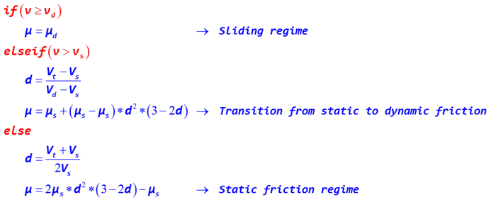
where,- is the current slip speed at the point of contact
-
is the stiction transition slip speed at which the full value of is used for the coefficient of friction
- is the dynamic friction slip speed at which the full value of is used for the coefficient of friction
- is the coefficient of static friction
- is the coefficient of dynamic friction
Figure 9 illustrates the functional relation between coefficient of friction and slip velocity
The blue curve depicts the full friction model covering all three regimes: static, transition to sliding friction, and sliding friction. This is the friction model applied when you select cff_type = "COULOMB_ON".- The static regime shown in light blue.
- The transition from static to dynamic friction show in white.
- The dynamic friction regime shown in light orange.
The red curve depicts the friction model covering only the sliding friction regime. This is the friction model applied when you select cff_type = "DYNAMICS_ONLY".
Figure 9. Coefficient of friction as a function of slip velocity - μ is the friction coefficient that is to be applied. As
shown in table 3, it is a function of the slip velocity and dependent on
the static and dynamic friction coefficients. The friction force opposes
the direction of the slip velocity. The table below lists the static and
dynamic friction coefficients for some common material pairs. The friction
values are extremely sensitive to surface coatings, so both dry and greasy
values are specified.
Material 1 Material 2 Coefficient of Friction Dry Greasy Static Dynamic Static Dynamic Aluminum Aluminum 1.05-1.35 1.4 0.3 Aluminum Mild Steel 0.61 0.47 Brake Material Cast Iron 0.4 Brake Material Cast Iron (Wet) 0.2 Brass Cast Iron 0.3 Brick Wood 0.6 Bronze Cast Iron 0.22 Bronze Steel 0.16 Cadmium Cadmium 0.5 0.05 Cadmium Mild Steel 0.46 Cast Iron Cast Iron 1.1 0.15 0.07 Cast Iron Oak 0.49 0.075 Chromium Chromium 0.41 0.34 Copper Cast Iron 1.05 0.29 Copper Copper 1 0.08 Copper Mild Steel 0.53 0.36 0.18 Copper Steel 0.8 Copper Steel (304 stainless) 0.23 0.21 Copper-Lead Alloy Steel 0.22 - Diamond Diamond 0.1 0.05 - 0.1 Diamond Metal 0.1 -0.15 0.1 Glass Glass 0.9 - 1.0 0.4 0.1 - 0.6 0.09-0.12 Glass Metal 0.5 - 0.7 0.2 - 0.3 Glass Nickel 0.78 0.56 Graphite Graphite 0.1 0.1 Graphite Steel 0.1 0.1 Graphite (In vacuum) Graphite (In vacuum) 0.5 - 0.8 Hard Carbon Hard Carbon 0.16 0.12 - 0.14 Hard Carbon Steel 0.14 0.11 - 0.14 Iron Iron 1 0.15 - 0.2 Lead Cast Iron 0.43 Lead Steel 1.4 Leather Wood 0.3 - 0.4 Leather Metal(Clean) 0.6 0.2 Leather Metal(Wet) 0.4 Leather Oak (Parallel grain) 0.61 0.52 Magnesium Magnesium 0.6 0.08 Nickel Nickel 0.7-1.1 0.53 0.28 0.12 Nickel Mild Steel 0.64; 0.178 Nylon Nylon 0.15 - 0.25 Oak Oak (parallel grain) 0.62 0.48 Oak Oak (cross grain) 0.54 0.32 0.072 Platinum Platinum 1.2 0.25 Plexiglas Plexiglas 0.8 0.8 Plexiglas Steel 0.4 - 0.5 0.4 - 0.5 Polystyrene Polystyrene 0.5 0.5 Polystyrene Steel 0.3-0.35 0.3-0.35 Polythene Steel 0.2 0.2 Rubber Asphalt (Dry) 0.5-0.8 Rubber Asphalt (Wet) 0.25-0.0.75 Rubber Concrete (Dry) 0.6-0.85 Rubber Concrete (Wet) 0.45-0.75 Sapphire Sapphire 0.2 0.2 Silver Silver 1.4 0.55 Sintered Bronze Steel - 0.13 Solids Rubber 1.0 - 4.0 -- Steel Aluminum Bros 0.45 Steel Brass 0.35 0.19 Steel(Mild) Brass 0.51 0.44 Steel (Mild) Cast Iron 0.23 0.183 0.133 Steel Cast Iron 0.4 0.21 Steel Copper Lead Alloy 0.22 0.16 0.145 Steel (Hard) Graphite 0.21 0.09 Steel Graphite 0.1 0.1 Steel (Mild) Lead 0.95 0.95 0.5 0.3 Steel (Mild) Phos. Bros 0.34 0.173 Steel Phos Bros 0.35 Steel(Hard) Polythened 0.2 0.2 Steel(Hard) Polystyrene 0.3-0.35 0.3-0.35 Steel (Mild) Steel (Mild) 0.74 0.57 0.09-0.19 Steel (Mild) Steel (Mild) - 0.62 Steel(Hard) Steel (Hard) 0.78 0.42 0.05 -0.11 0.029-.12 Steel Zinc (Plated on steel) 0.5 0.45 - - Teflon Steel 0.04 0.04 0.04 Teflon Teflon 0.04 0.04 0.04 Tin Cast Iron 0.32 Titanium Alloy Ti-6Al-4V(Grade 5) Aluminum Alloy 6061-T6 0.41 0.38 Titanium Alloy Ti-6Al-4V(Grade 5) Titanium Alloy Ti-6Al-4V(Grade 5) 0.36 0.3 Titanium Alloy Ti-6Al-4V(Grade 5) Bronze 0.36 0.27 Tungsten Carbide Tungsten Carbide 0.2-0.25 0.12 Tungsten Carbide Steel 0.4 - 0.6 0.08 - 0.2 Tungsten Carbide Copper 0.35 Tungsten Carbide Iron 0.8 Wood Wood(clean) 0.25 - 0.5 Wood Wood (Wet) 0.2 Wood Metals(Clean) 0.2-0.6 Wood Metals (Wet) 0.2 Wood Brick 0.6 Wood Concrete 0.62 Zinc Zinc 0.6 0.04 Zinc Cast Iron 0.85 0.21 - For 2D curve contact the contact point is determined as the point of
maximum penetration in direction of the contact normal. For configurations
that yield deep penetrations between curves it is possible that this point
is not uniquely defined.
In such a situation the parameter contact_stability_2d can be added. The parameter adds a virtual spring in the contact point calculation that pulls the point of contact in direction of center of mass of the overlapping area. A larger value yields a stronger spring and thus a larger stability. The penetration depth is calculated based on the distance in normal direction of the contact point found in this way.
If the contact_stability_2d is set to zero, contact point calculation will be skipped and the center of mass of the overlapping area will be used instead. In this case penetration depth will be calculated based on the overlapping area. This value usually slightly underestimates the true penetration depth.
- The normal direction on the surface of a solid flexible body is always pointing outwards (away from the body material). In cases where the flexible body is represented by a shell, the direction of the normal is defined through the order of the GRID points used in the definition of the SHELL elements inside the H3D file. Withi_flip_flex and j_flip_flex, you can flip the direction of the normal to accommodate for contact from the other side of shell elements.

