OS-V: 1200 Bar Impact
Taylor TestAn elastic-plastic cylindrical bar impacts a rigid planar target with a high velocity (120-266 m/s). Verify the deformation results with the real test results.

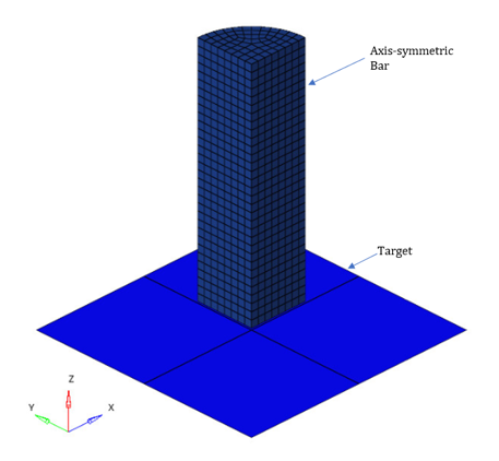
Figure 1. FE Model
Cylindrical bar: length L=16mm, radius R=4mm
Benchmark Model
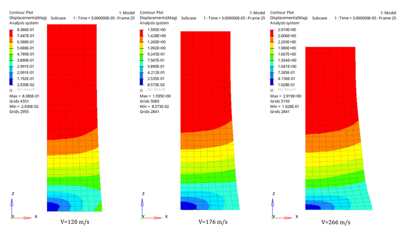
The finite element model, as shown in Figure 1 is meshed with first order CHEXA elements (32 elements along its length and 8 elements along its radius). The bar to target contact is frictionless. The appropriate boundary conditions are applied on the symmetry planes of the quarter model. The cylindrical bar is imparted 3 different velocities of 120.170 and 266 m/s.
Material
- Bar (Elastic-Plastic Stainless Steel) Material Properties
- Young's modulus
- 2.10E+05 N/mm2
- Poisson's ratio
- 0.3
- Density
- 7.85E-09 ton/mm3
- Johnson & Cook Plasticity Parameters
- A
- 350
- B
- 1000
- n
- 0.65
- C
- 0.07
- m
- 1
Results
| Impact Velocity | Length/Radius | Reference Value | OptiStruct Results | |
|---|---|---|---|---|
| Absolute Value | Error % | |||
| 120 m/s | Length | 15.3 | 15.1 | -1.30 |
| Forward Radius | - | 4.433 | - | |
| Mid-Length Radius | - | 4.050 | - | |
| 176 m/s | Length | 14.6 | 14.320 | -1.90 |
| Forward Radius | 4.8 | 4.753 | -1.04 | |
| Mid-Length Radius | 4.1 | 4.128 | +0.68 | |
| 266 m/s | Length | 13.3 | 12.980 | -2.40 |
| Forward Radius | 5.5 | 5.362 | -2.50 | |
| Mid-Length Radius | 4.2 | 4.335 | +3.21 | |

Figure 2. Deformed Shapes of the Bar
Model Files
Refer to Access the Model Files to download the required model file(s).
- Bar1.fem
- Bar2.fem
- Bar3.fem
Reference
Calleja P., Terras C., Dormeval R., Ansarf J.-P. (CEA): “Taylor's test on aluminum, copper and stainless steel”, Physics Journal, colloquium C5, supplement to no. 8, Vol. 46, August 1985, pp. C5-91 to C5-99