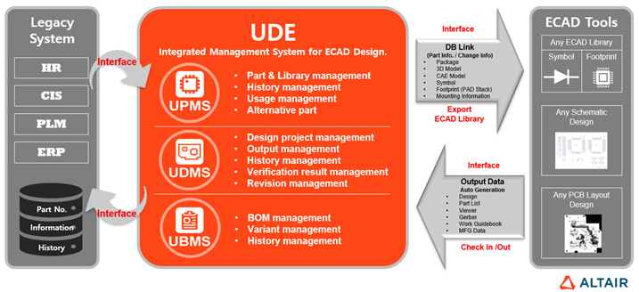
PollEx UDE is Optimized unified management system for
electrical-design in the mechanical-design based PLM system.
The UDE Platform provides Parts / Library, Design Data, BOM Management functions for
the required product and history management stages. UDE supports the PollEx product interface.
The UDE consists of three main modules: Unified Part Management System (UPMS),
Unified Design Management System (UDMS), and Unified BOM Management System
(UBMS).
UPMS: Standardization and management module for library and part catalog information
used for electrical design in the system.
UDMS: Unified management system which manages design data from creation to finish
through managing each development process. Automated checking system for suitability
of part and consistency between schematic, PCB and BOM.
UBMS: Generating BOM with the part list, which is extracted in design check in
process, and supporting edit, report, manage variant and back annotation
functions.
UDE System requires separate server installation (JAVA, Apache Tomcat, DB (MS-SQL,
ORACLE, and so on).
This tutorial describes how to use the environment after it has been configured.
UDE Platform
Figure 1.
This document is based on the PollEx UDE system built using
MS-SQL database, and download and install the installation file and guide document
from https://connect.altair.com before startup.
Login to UDE
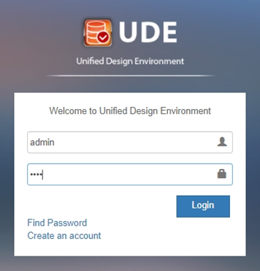
UDE is an application used by the Web and is available through Login. Invoke a Chrome
web-browser and enter the server URL. If you don’t know the URL, contact your system
manager.
Server URL: http://[UDE SERVER IP]:[Port Number]/UDE/
For example, http://10.20.30.40:8080/UDE
To use the PollEx UDE, users with respective functional
permissions should be registered to prepare, review, and approve drawings or
documents. However, in this document, we will use the user who has full privileges
for explanation and about the registration of the user will be explained at the end
of this document.
Login using the user account and password as below.
ID: admin
Password: 1234
Figure 2.
Note:
Because the admin account can work with system impacting contents, the account
will be expired in 30 days to prevent the system failure by unintended
operations.
After the expiration, you should change the password to use the admin
account.
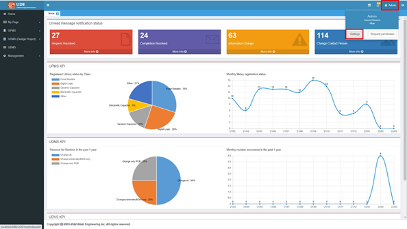
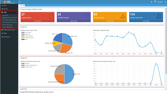
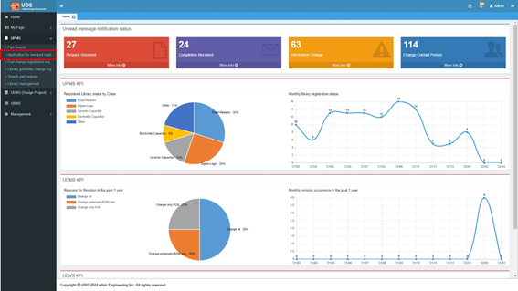
Home
Check messages from system such as the results of your own request and other’s
request for your approval, change information of parts use, and your designation as the
person in charge of the development process.
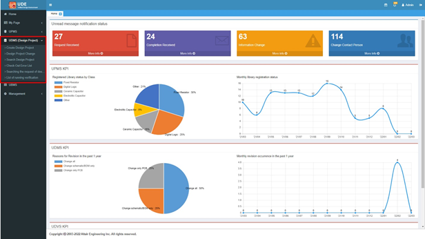
In Home, you can also check the KPIs for the status in Parts Registrations and Design
Revisions.
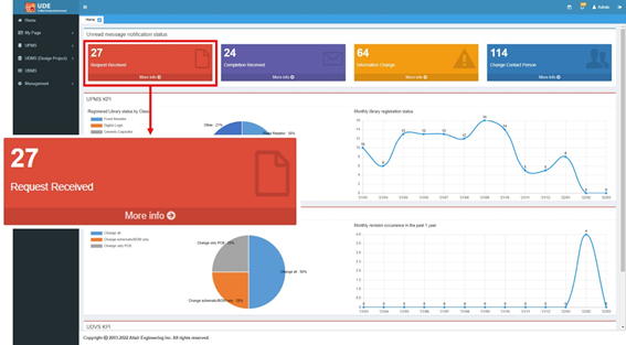
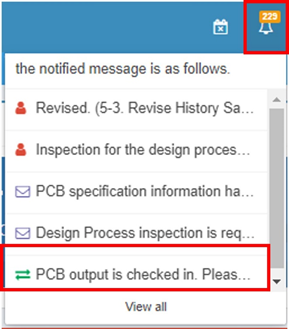
Check unread messages.
Check the message box for messages.
If there are messages, the message box will indicate the
number.
Click More info to check messages.
Figure 3.
Unread message will be listed in Notified message list.
The number of unread messages may vary depending on the
situation.
Click the message list to check what is
requested, and to proceed with the requested item.
Depending on the message, the displayed items may vary.
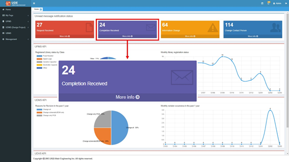
Check results of your request.
Check the Completion Received message box for messages.
If there are messages, the Completion Received message box will show
the number of messages.
Click More info to check messages.
Figure 4.
Unread messages are shown in Notified message list.
Click the message list to check the result of
your request.
Depending on the message, the displayed items may vary.
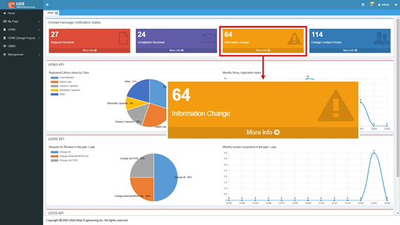
Check information of preventing and releasing part.
Check the Information Change message box for messages.
If there is any message, the message box shows the number of
messages.
Click More info to check the message.
Figure 5.
Unread messages are shown in Notified message list.
Click the message list to check
preventing/releasing information of part.
In the Design Detail Information tab, click .
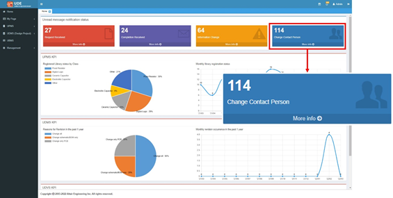
Check changed information of person in charge.
Check the Change Contact Person message box for messages.
If there are messages, the message box shows the number of
messages.
Click More info to check a message.
Figure 6.
Unread messages are shown in notified message list.
Click the message list to check the changed information of person in
charge.
In the Design Detail Information tab, click .
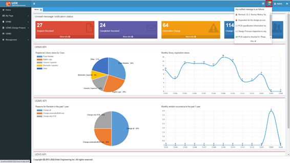
Check all messages.
In the top-right, click .
Figure 7.
Click the message list to check detail
information of the message.
Figure 8.
In the Design Detail Information tab, click .
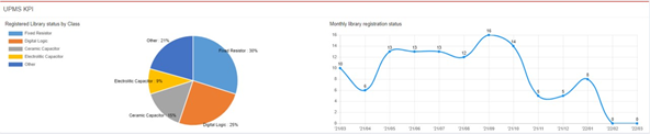
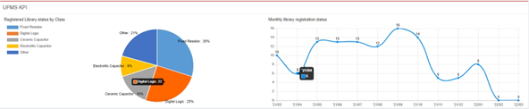
UPMS KPI
Check the status of parts registration. The part class items in the KPI are
specialized when deploying UDE system and cannot be changed.
Note: The graph of the KPI may have a different shape depending on the time of
installation. Figure 9.
Move your cursor over the chart to display the count of parts registered in
the corresponding part class.
Figure 10.
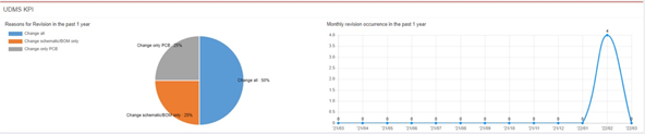
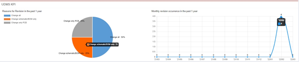
UDMS KPI
Display the status of the causes of the revisions of the design projects over the
past year.
The reasons for revision are specialized when deploying UDE system and cannot be
changed. In the samples which are copied during the installation don’t have revision
contents, so there is no data, but for example, it looks like the following. Figure 11.
In the UDMS KPI, move your cursor over the chart to display the count of design
projects in the corresponding cause. Figure 12.
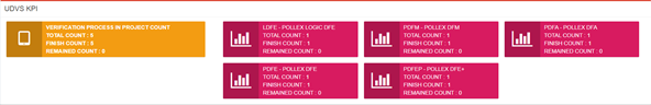
UDVS KPI
You can verification check progress.
These items are specialized when deploying UDE systems and cannot be changed.
Depending on the system status, the KPI may be changed. Figure 13.
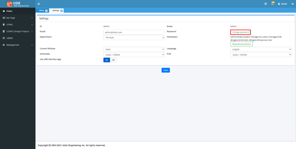
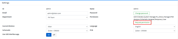
Set user environment.
Click the username in the top-right and select
Settings from the context menu.
Figure 14.
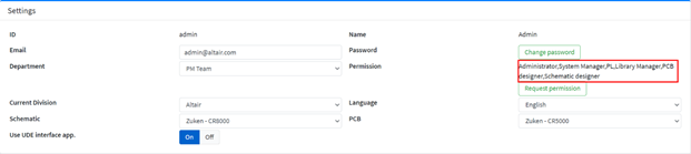
Settings for user’s environment menu appears. Figure 15.
To change password, click Change Password.
Enter the current and new password and click
Change.
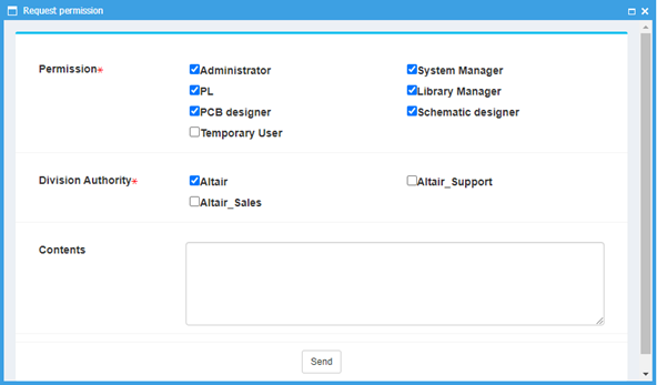
To request authority, click Request
permission.
Figure 16.
From the Request permission dialog, disable the
Temporary User checkbox and click
Send.
Figure 17.
If a mailing system had been set during the installation, the
request is sent to the administrator via e-mail, and if the
administrator finds out about the permission request, the administrator
can grant permissions for the user.
Note: For explanation, assume that
the system manager has received an email for requesting permission
and explain the process of approving user permissions as
follows.
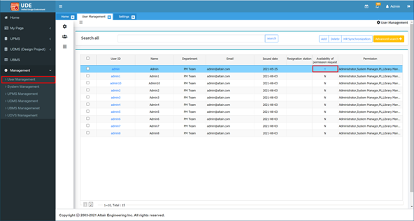
Select Management > User Management.
In the Availability of permission request column, click
Y.
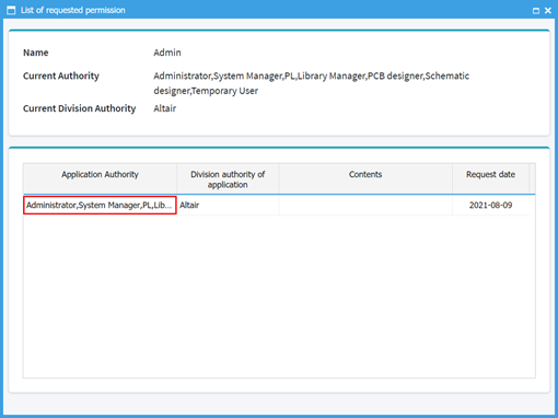
The List of requested permission dialog
opens. Figure 18.
In the List of requested permission dialog, click
the content of the Application Authority column.
Figure 19.
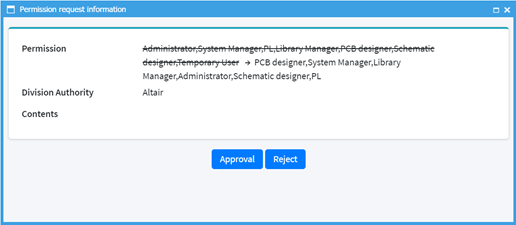
Check the requested permission and click
Approval.
Figure 20.
If the permission request is approved by the administrator, it is
reflected only after logout and login again.
Figure 21.
Unified Part Management System
Unified Part Management System (UPMS) is a management module by standardizing part
library and catalog information used in electronic circuit design in the system.
By registering parts used for electronic circuit design in UDE System, you can manage
the revision history and usage of parts. Figure 22.
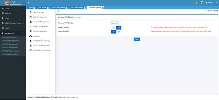
In the Setting UPMS Environment, turn on the
Use create UPF option.
Click Save.
Figure 23.
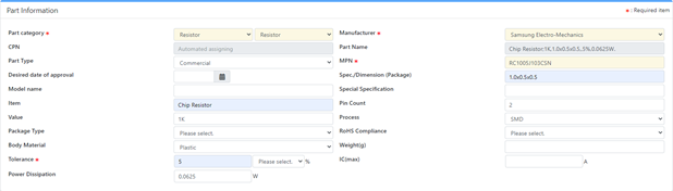
Application for new part registration.
Select UPMS > Application for new part registration and enter the information of the part.
Figure 24.
Depending on the part category selection, additional
characteristics are added in the input fields. If you enter as much
information as possible during new part registration, it will be easier
to manage and track the part. Enter the part information as shown in
Figure 25. Figure 25.
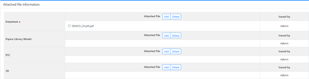
Datasheet is a mandatory field because a library manager cannot
determine the part shape without the datasheet. Any file format can be
attached. Figure 26.
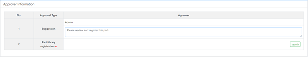
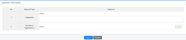
A part can be used after requesting registration by hardware
engineer and approved by library manager.
Within this process, you can
prevent the duplicated registration of a part and the inconsistency
within the part standardization. Figure 27.
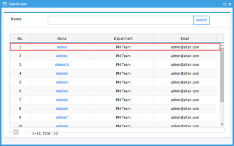
You can search and select the library manager. Click
Search and select the library manager. In
this document, select the current user as library manager for
convenience. Figure 28. Figure 29.
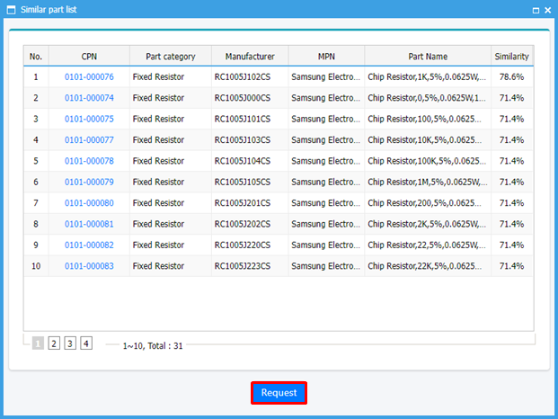
The UDE supports to view the similar parts already registered
with the part requested for registration.
If there is a part
which is almost same with the part requested, use the part
registered already. Figure 30.
Send new part registration request.
In the Similar part list dialog, click
Request.
Because there are similar parts in the database, UDE asks you to apply
or not.
Click OK.
Click OK.
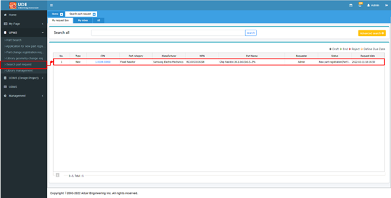
Search part request.
From the menu bar, click UPMS > Search part request.
In the menu, you can check the items requested, items requiring
approval, and all items requested for approval.
Click My Request box.
Figure 31.
Click CPN to display detail request
information.
Note: The CPN as it will be used in the part search function that
follows this tutorial.
Click in the Requested Information
tab to close.
Check the parts requested.
Select My inbox to display the list of requested
parts needing approval.
This function is only available for those with Library Manager
authority. Figure 32.
Click CPN to display detail request
information.
The
library manager reviews the requested contents and should enter the
symbol and footprint information.
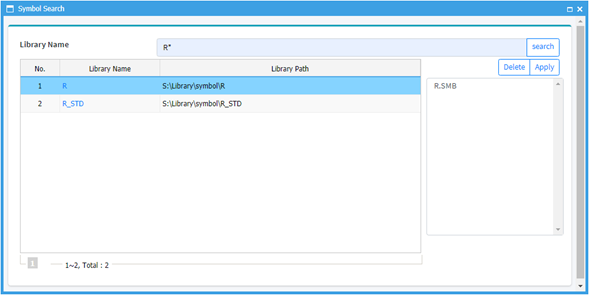
Click Search in the right side of Symbol of
Library Information.
Enter R* in the search box and click
Search.
In the result, select R for adding logic symbol
of the part and click Apply.
Figure 33.
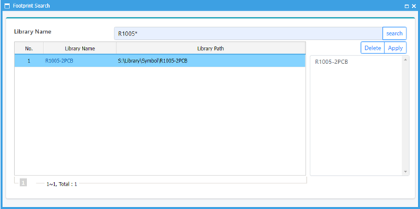
Click Search in the right side of
Footprint.
Enter courier in the search box and click
Search.
In the result, select R1005-2PCB for changing
footprint of the part and click Apply.
Figure 34.
After specifying the library, leave a comment and click
Approval.
Click Approval to approve the
request.
Note: When a part is approved by the library manager, PollEx UDE is invoked to create the part library
file (*.upf) automatically. The library manager
needs to wait until the part creation is completed and UPE is
finished.
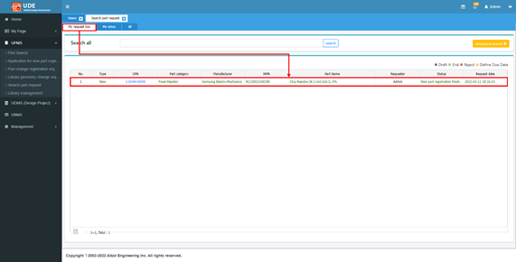
Confirm the approval of the requested part.
Click My request box to display the requested
list.
The requests that have been approved are changed to green letters. Figure 35.
Click CPN to check the contents.
Part Search.
Click Part Search to find parts.
Enter the CPN of the part created in step 4 in the search box and click
Search.
Search 1-0104-00000.
Figure 36.
Click CPN to display the information of the
part.
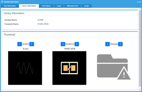
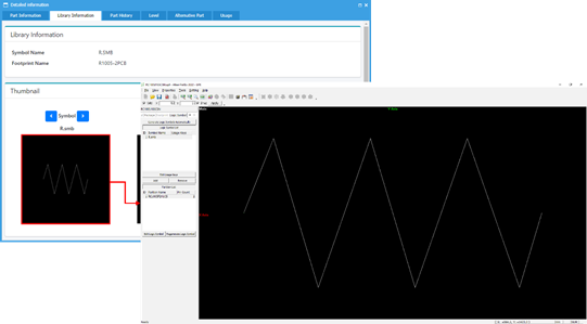
Check the part information.
Check the library information.
Click Library Information to check the library
of logic symbol and footprint.
The libraries for logic symbol and footprint are generated during the
part registration approval, but the package is not generated at that
time, so the package library is not shown. You need to add a package
library for the part after creation and to edit the library, refer to
the PollEx UPE user
guide. Figure 37.
Click the image of the logic symbol to invoke PollEx UPE.
You can check more information using the PollEx UPE. Figure 38.
From the menu bar, click File > Exit to close the PollEx UPE.
Check the Part History.
Click Part History to see the history from the
creation to discontinuance and the usability of the part.
Click the Request No. for more
information.
Click to
close the information window.
Check the level and unit price.
Click Level to see the level and unit price of
the part.
The level means the usability of the part.
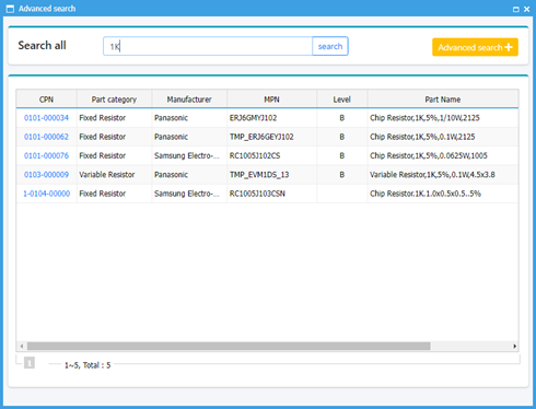
Check the Alternative Part.
Click Alternative Part to see the alternative
parts which can replace this part.
Click Add.
Enter 1K in the search box and click
Search.
Figure 39.
Select the CPN of the 0101-000034 part and click
OK in the
message box.
0101-000034 part is added as an alternative part.
Click CPN to display detail information of the
alternative part.
Click to
close.
Check the Usage.
Click Usage to check the designs in the database
which are including the part.
Because this part is just created, so there is no design which uses
this part.For example, if you search 0202-000037 part,
you can see the list of design projects where the part was used as
below.
Click to
close.
Click in
the upper-right side to close all dialogs.
Library Management of UPMS
Manage the part library and it can be only accessed by the library
manager.
Click Library management from the left side menu.
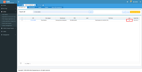
Part Library Lock.
The library manager can lock a specific part so that users cannot use the
part.
Click Part Library Lock and search the part
previously registered.
Search 1-0104-00000 part.
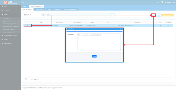
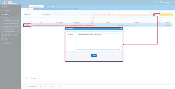
Lock a part.
Check the checkbox of the part.
Click Lock.
In the Lock Library dialog, click
Lock.
Figure 40.
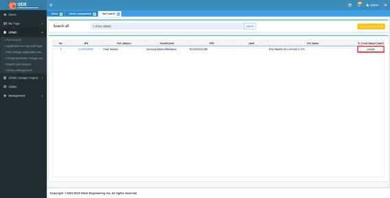
The Lock status of the part is changed to Y. Figure 41.
If a part is locked, the display in the To Circuit Design (Insert) is
changed from Insert to Locked. Figure 42.
Unlock a part.
From the left side menu, click Library
management.
Check the checkbox of the part.
Click Unlock.
In the Lock Library dialog, click
Unlock.
Figure 43.
Lock status of the part is changed to N. Figure 44.
Edit part library.
Select Edit part library and search a
part.
Search 1-0104-00000 part.
Click CPN to display the part
information.
Change part library information.
In this menu, you can change the part library information and assign the
official CPN.
Scroll down the page and click
Change.
Click search to search a CPN from the neutral
database imported from corporate system.
Select 0101-000092.
Click the CPN.
Scroll down and click Save.
Click to
close all tabs.
UDMS Setting for Automatic Verification
To use automatic verification during the design check-in process, you must set it up
in advance.
After you set this up, the verification stage is set in the design project,
verification is automatically executed when the design is checked in.
Note: It is because UDE use PollEx Verification, PollEx should be installed to execute
the automatic verification.
Go to the folder where PollEx is installed.
Using a text editor, open the
PollExService_Environment.ini file and add a
verification working folder to EXPORT_WORK_DIRECTORY.
The folder should be an existing folder. Example:
EXPORT_WORK_DIRECTORY=D:\UDE_root\VerificationOutputs
Save and close the file.
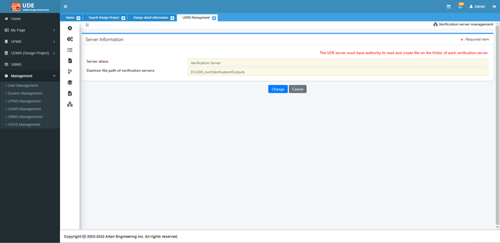
Log in to UDE and select Management > UDMS Management > Verification server management.
Click Add and enter the information:
For Server alias, enter Verification
Server.
For Daemon file path of verification server, enter the folder path
defined in the PollExService_Environment.ini
file.
Execute an explorer and change folder to C:\Program
Files\Altair\2022\PollEx.
Double-click the PollExServiceMgr.exe file to execute
PollEx service daemon.
Unified Design Management System
Unified Design Management System (UDMS) is a unified electrical design management
system through check in and out function onto server for schematics and PCBs.
By centralized managing the design data, the UDMS can efficiently manage all design
data instead of managing by each personnel.
It can prevent from the problems occurred due to the individual data management by
each developer.
In UDMS, one PCB design data is managed as one design project.
Note: To check in or check out a design data for testing UDMS, download and extract the
tutorial sample files from Connect to the folder as below. If the folder doesn’t
exist, create it.
C:\ProgramData\altair\PollEx\2022\Data\TutorialSample.
Click UDMS (Design Project).
Figure 46.
Create Design Project.
Each design project can be categorized by a customer, product group, or
product type.
Click UDMS (Design Project).
Click Create Design Project and enter the
information of the project such as name, schedule, type, and so on like
below.
Items marked with * are mandatory.
Note: As this is a test, attach an
arbitrary file for the Development
Specification.
Click Process Setting.
Click Import settings to use the default process
setting.
The default design process scheme includes Schematic Design, Schematic
Verification, Part List, PCB Design, PCB Verification, CAE, Allowable
Error checking, and Sample PCB Order. These processes can be modified
depending on the company’s requirements and linked with the corporate
system such as PLM or ERP. But in this document, we’ll use the default
process.
Select the box of Schedule and specify each schedule of the process and
specify the current user as the project leader by clicking .
Click Registration.
In the Search Design Project, you can find the project just
created.
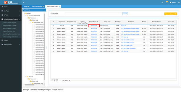
Search Design Project.
When the project registration is finished, you can see the project information
in the project search page.
Click the design project number to check the project information.
Figure 47.
You can check the project information.
Click Process Setting to check the processes and
schedules.
Click Schedule status to check the development
progressing status.
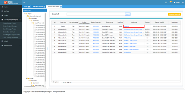
Click to
close.
Click the Model name of the project to check the design detail
information.
Figure 48.
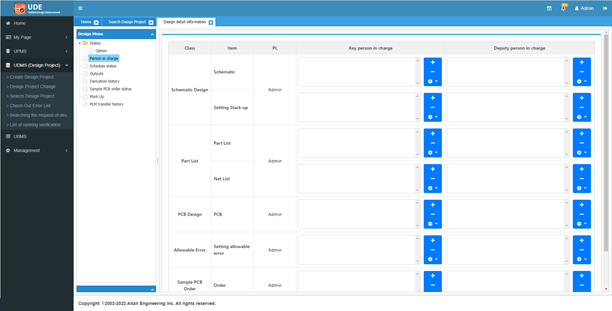
Assign the person in charge.
For each design stage, assign the person in charge to perform the
development.
From the Design menu, select Person in
charge.
Figure 49.
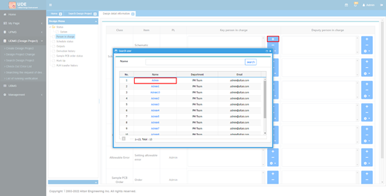
Click to
assign the key person in charge and select Admin from the list.
Figure 50.
In the same way, assign all key and deputy person in charge as
Admin and click
Registration.
The messages that the person in charge have not been designated are
removed. Figure 51.
Schematic Check-Out / Check-In.
You need to check-out the design to start schematic design. After finishing
the schematic design, you can check-in to store the design and generate needed
outputs.
Click Schematic Design.
Figure 52.
Click Check-out.
Click OK.
The information of the design checked out is displayed. When checking
out, the check-in data is downloaded. However, no data is downloaded for
the first time since the creation of the design project. You can
continue without any files downloaded.While uploading the schematic design
data, UDE automatically converts the schematic data made by CAD tool
into a PollEx Logic data (SDBB) and generates part list and netlist. The
generated data is shown as an icon in the data column. But, for testing,
we will use PollEx Logic Data (SDBB) instead of CAD data for check
in.
Select PollEx in the Check-in file type and
click Check In.
In the Check In dialog, click
Search.
Navigate to
C:\ProgramData\altair\PollEx\2022\Data\TutorialSample
folder, select PollEx_New_Sample.sdbb, and click
OK.
During the check in, UDE makes needed outputs such as netlist and part
list automatically. You can check the status with progressive
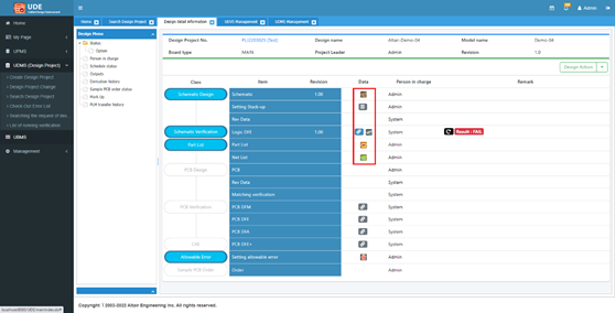
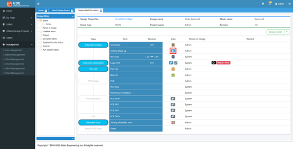
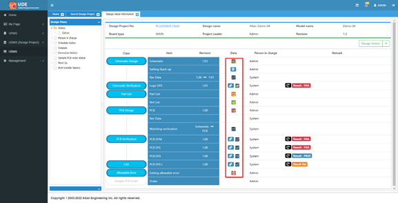
bar.After generating part list and netlist, Schematic
Verification is executed automatically.After check-in, the icons of extracted
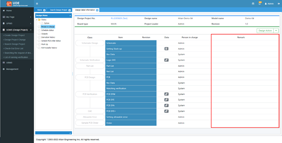
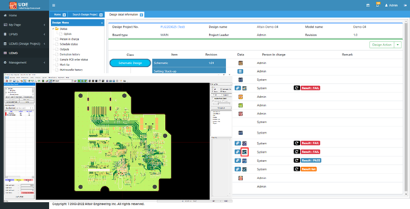
outputs are shown in the design status page. Figure 53.
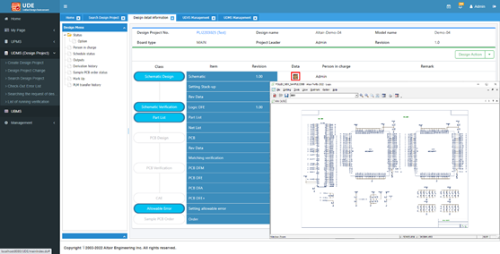
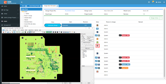
Click to
view the schematic data using PollEx Logic.
Figure 54.
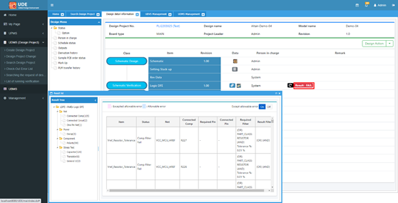
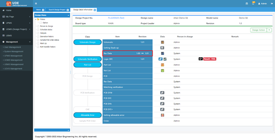
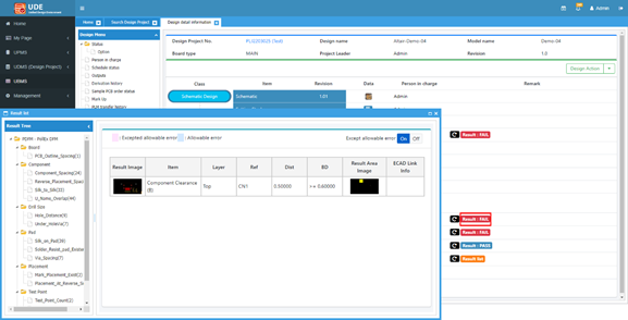
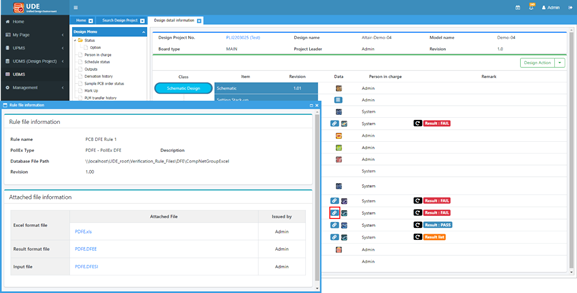
Click to
see the result.
Figure 55.
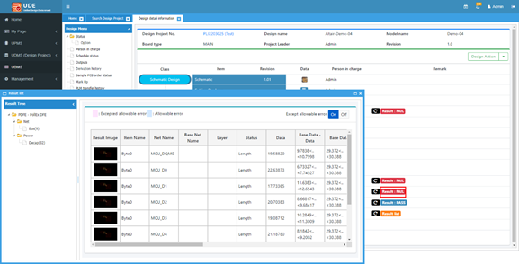
The sign
that means the schematic verification using PollEx Logic DFE has failed
item which doesn’t meet the verification condition.
For more detail about the result, click to
execute PollEx Logic DFE.
For more information about PollEx Logic DFE, refer to the Logic DFE user
guide. Figure 56.
Close PollEx Logic DFE and click to
view the part list data.
The part list will be shown as a BOM list format. Figure 57.
Close the part list dialog and click
Schematic Design and Check
Out again.
Figure 58.
Assume that the schematic data is modified, check in the schematic
data again.
Select PollEx in the Check-in file type and
click Check In.
In the Check In dialog, navigate to
C:\ProgramData\altair\PollEx\2022\Data\TutorialSample
folder, select PollEx_New_Sample.sdbb, and click
OK.
The Rev Data item is changed as below. Figure 59.
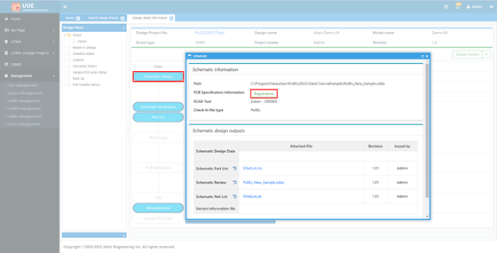
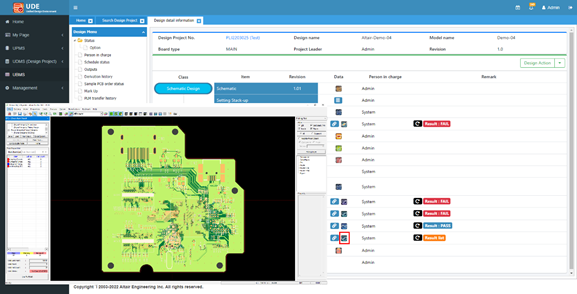
After finishing the schematic design, you can start the PCB
design. To start the PCB design, the PCB specification should be
specified first.
Select Schematic Design and click
Registration of the PCB Specification
Information.
Figure 60.
Click search and select PBA
No. and PCB No., and specify the
PCB specification information as shown below,
and click Registration.
Click OK and close the PCB
Specification Information and Schematic Information
dialog.
Click to
set up the layer stack up.
Figure 61.
Select 6L_4.0.
You can
check and modify the layer stack up of the PCB design.
Click Cancel and close the Setting
Stack-up dialog.
PCB Check-Out / Check-In.
You need to check-out the design to start schematic design. After finishing
the schematic design, you can check-in to store the design and generate needed
outputs.
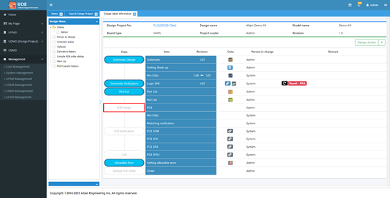
Click PCB Design to start the PCB design
stage.
Figure 62.
Click Check Out.
After check-out, the status is shown in the design status
page.Assume that the PCB design is completed.
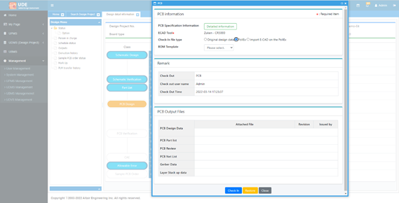
Click PCB Design and select
PollEx in the Check-in file type and click
Check in.
Figure 63.
Click Search, navigate to
C:\ProgramData\altair\PollEx\2022\Data\TutorialSample
folder, select PollEx_New_Sample.pdbb, and click
OK.
While
uploading the PCB design data, UDMS will convert to PollEx design file
and update the part and net lists. After uploading the PCB design data,
PCB Verification is started automatically.
When the verification is finished, the generated outputs are
listed in the Data column. Figure 64.
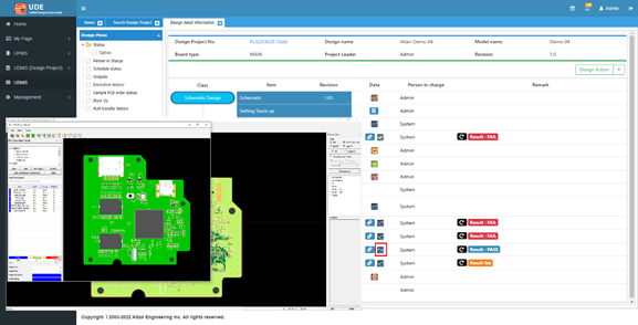
Click to
see the PCB design.
Figure 65.
For more detail about the PollEx PCB, refer the PollEx PCB user
guide.
Close PollEx PCB.
In the PCB Verification, you can see the sign
that means the PCB verification using PollEx DFM and PollEx DFE have
failed item which don’t meet the verification condition.
Click of
the PCB DFM item to see the DFM verification result.
Figure 66.
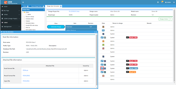
Close the result dialog and click of
PCB DFM to see more detail information using PollEx DFM.
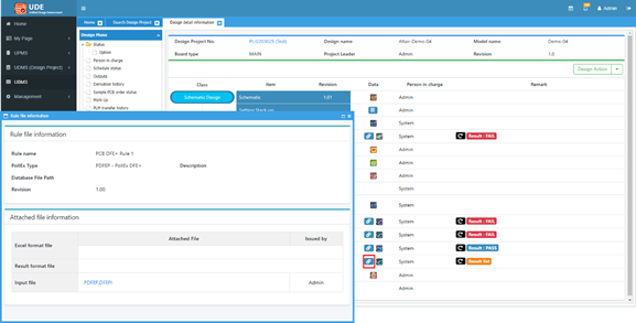
Close PollEx DFM and click of
PCB DFM to see the DFM input settings.
Figure 67.
Close the DFM input setting dialog and click
of
the PCB DFE item to see the DFE verification result.
Figure 68.
Close the result dialog and click of
PCB DFE to see more detail information using PollEx DFE.
Figure 69.
Close PollEx DFE and click of
PCB DFE to see the DFE input settings.
Figure 70.
Close the DFE input setting dialog.
It is because the PCB DFA verification has no fail result the result
icon is displayed as , and
you cannot click the icon. But you can check the detail information
using PollEx DFA.
Click to
see the detail information.
Figure 71.
Close PollEx DFA and click of
PCB DFA to see the DFA input settings.
Figure 72.
Close the DFA input dialog and click of
PCB DFE+ item to see the DFE verification result.
Figure 73.
Close the result dialog and click of
PCB DFE+ to see more detail information using PollEx DFE+.
Figure 74.
Close PollEx DFE+ and click of
PCB DFE+ to see the DFE+ input settings.
Figure 75.
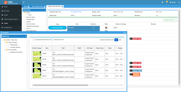
Close the DFE+ input setting dialog and click
to
set up the allowable error.
Figure 76.
If an error is set to an allowable error, the verification does not
determine the error for the same value. Select PCB DFM > Component_Spacing(24) and check the first and second items and click
Save.
Close the setting dialog and click of
PCB DFM.
Figure 77.
The DFM verification is rerun.
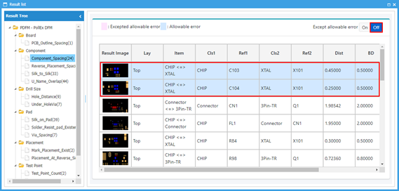
Click to
check the result.
You can see the first (C103 and X101) and second item (C104 and X101)
are removed in the error list.
Switch to Off of the Except allowable error to
see the allowable error.
This means the two items are no longer determined to be errors. Figure 78.
Close the result list dialog.
EBOM (Schematic & PCB Part List) review.
When the PCB design is checked in, the physical information such as placement
coordinates, angles and placement sides are added to the part list.
Click to
check the part list.
Figure 79.
Move the scroll bar at the bottom to the right to see the
additional information such as part coordinates, process, and so on are
shown in the part list.
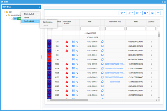
Assume that all design process is finished, place the cursor over
and
click the right button of mouse and select Confirm BOM > Confirmation.
Figure 80.
Close the part list.
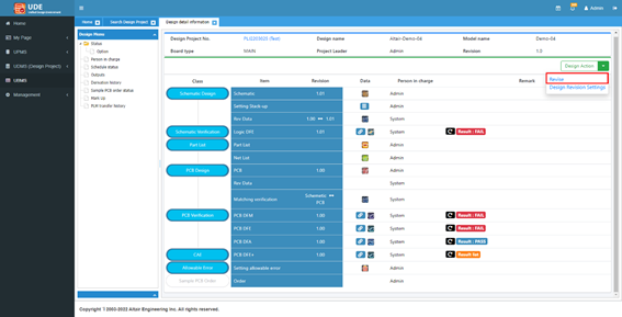
Revise design.
In the section 4. Schematic Check-Out / Check-In, if a schematic data is
checked out and checked in for modification, the minor revision is changed (for
example, 1.00 to 1.01). But after finishing whole design, a revision is needed
to modify the design and the major revision is changed (for example, 1.01 to
2.00).
Click of
Design Action and select Revise.
Figure 81.
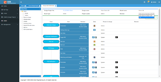
Enter the revise information as shown below and click
Revise.
The revisions of the schematic and PCB data are
changed to revision 2.00.
In the Revision selection, select 1.0 to see the
1.0 revision.
Figure 82.
The design status is changed to revision 1.0. After revision, all
processes are same with previous revision.
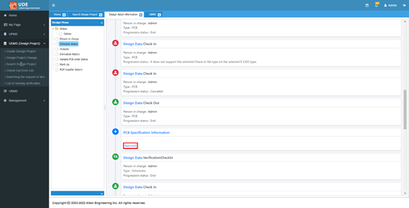
Check design schedule.
Click Schedule status in the Design Menu.
You can see the schedule information of the design
project.
Scroll down and click Read more in the PCB
Specification Information.
Figure 83.
You can see the PCB Specification Information.
Close the window.
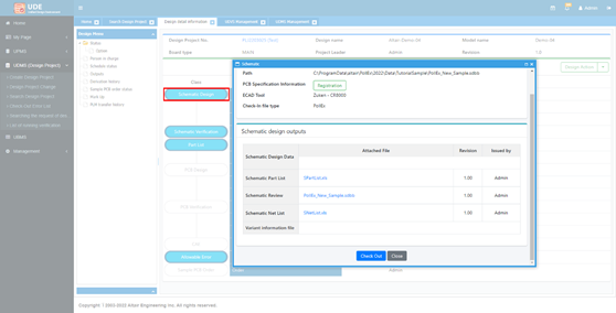
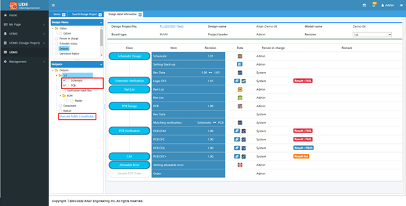
Check design outputs.
Click Outputs in the Design Menu and enable the
Schematic and PCB
checkboxes.
Click Execute PollEx CrossProbe.
Figure 84.
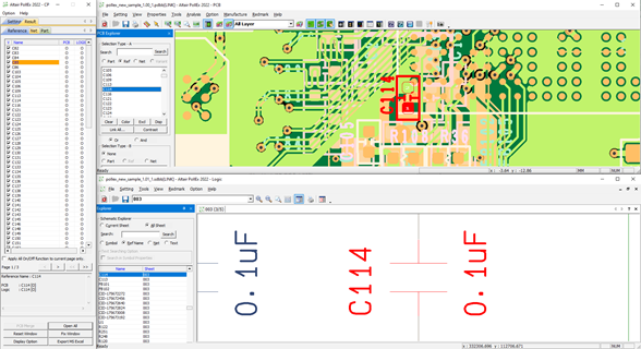
The PollEx CrossProbe is invoked and compare the schematic and PCB
data. Figure 85.
Close the PollEx CrossProbe.
Unified BOM Management System
Unified BOM Management System (UBMS) is a unified BOM management system which
generates BOM data by using the part list created during the design check-In
process.
UBMS supports to manage, modify, report the BOM data and to create variant BOM data.
Many companies create the BOM data manually which takes lots of time and errors, but
these problems can be prevented through the UBMS.
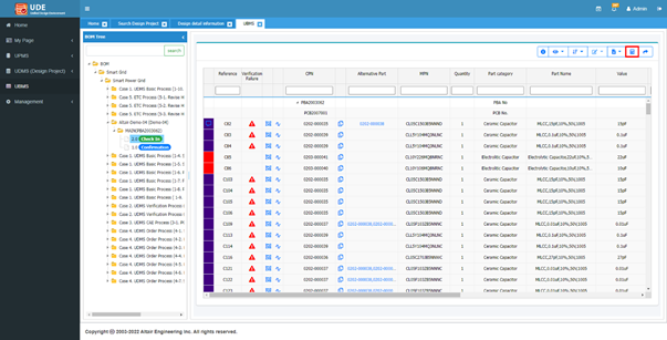
Select UBMS and select Altair-Demo-04(Demo-04) > MAIN > Add sensor function (2.0).
Edit BOM.
To modify the BOM data, you should check-out the data. You can sort the list
by reference name or part number. For editing BOM data, you need to check out
the BOM data.
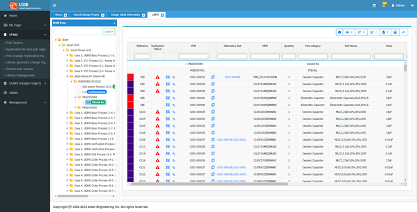
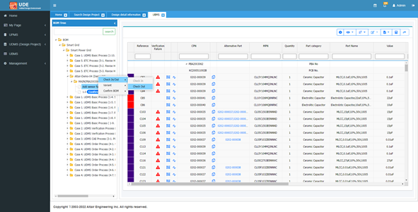
Place the cursor over Add sensor function(2.0) item, right-click, and
select Check In/Out > Check Out.
Figure 86.
The page changes to the BOM editable environment.
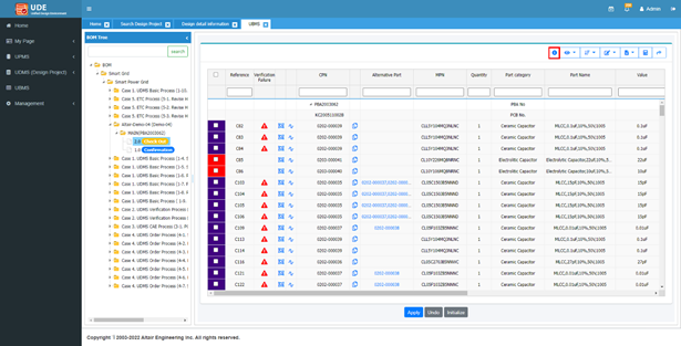
Check design details.
Click to
check the detail information.
Figure 87.
Click in
the Design detail information tab to close and select UBMS tab.
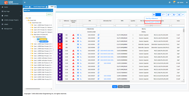
View Mode Control.
Currently, the BOM list is shown by the Reference order.
Click and
select Sort by part number to change the view
mode.
Figure 88.
Then the list is sorted by part number.
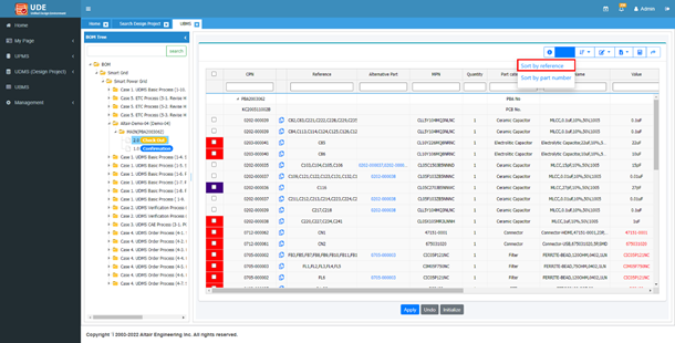
Edit part.
Using the Edit function, you can add, change, and delete parts for electrical
parts. You can also add and edit the non-electrical parts such as screws,
heat-sinks, and other mechanical parts which are not included in the
design.
Select View Mode > Sort by reference.
Figure 89.
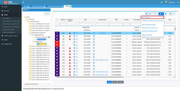
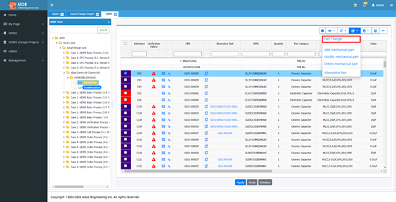
Part Change.
In the BOM edit mode, if you want to change a part, only the parts which have
the same footprint are listed on the table. This is because a critical defect
occurs if the footprint is different from the original part.
Select the C82 part and select Edit > Part Change.
Figure 90.
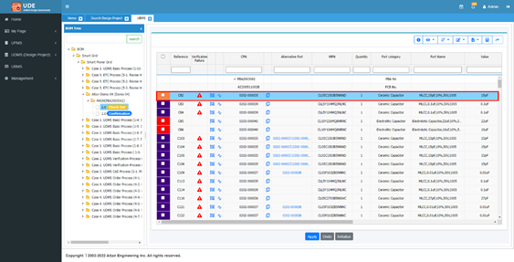
Search and select 0202-000035 part to
change.
Now C82 is changed to 0202-000035 part. Figure 91.
Click Apply to apply the change
information.
Click OK to apply.
Click OK to finish and the BOM is checked in
automatically.
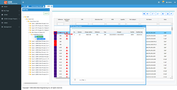
You can check the editing history by part.
Click of
C82 reference to check the history.
Figure 92.
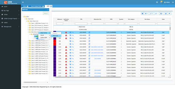
Edit mechanical part.
Mechanical part means part which is not included in the schematic or PCB such
as screw or heatsink or label. To add a mechanical part to BOM, check out the
BOM again.
Select Altair-Demo-04 > MAIN > 2.0, right-click, and select Check In/Out > Check Out.
Figure 93.
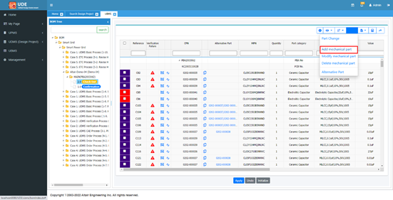
Select Edit > Add mechanical part.
Figure 94.
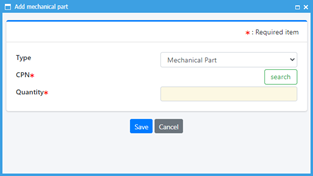
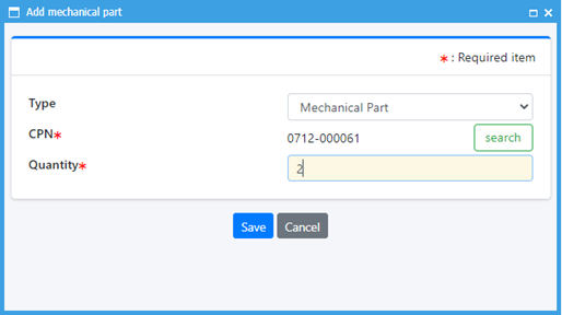
For Type, select Mechanical Part and click
search.
Figure 95.
Select 0712-000061 part to add.
Even though this part is not a mechanical part, for tutorial assume
this part is a mechanical part.
For Quantity, enter 2 and click
Save.
Figure 96.
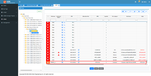
You can see the added mechanical part in the BOM list.
Figure 97.
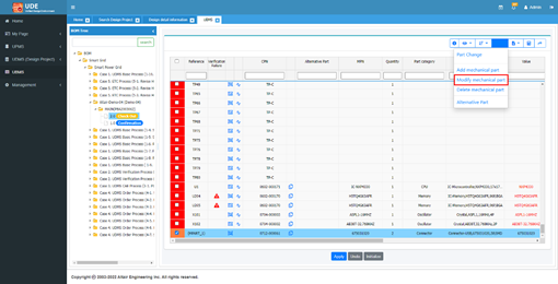
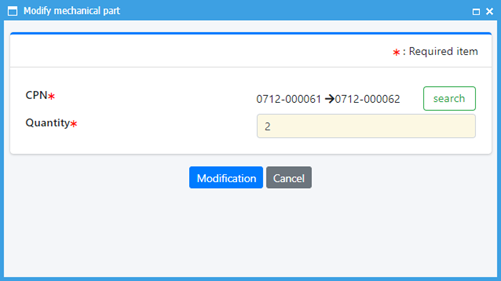
Select the mechanical part and select Edit > Modify mechanical part.
Figure 98.
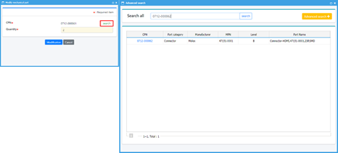
In the Modify mechanical part dialog, click
search and select
0712-00062 part.
Figure 99.
Click Modification.
Figure 100.
The mechanical part is changed.
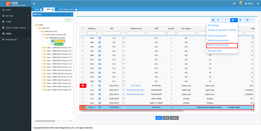
Select the mechanical part and select Edit > Delete mechanical part.
Figure 101.
Click Apply.
Then the BOM is checked in automatically.
Add and modify alternative parts.
You can see the added alternative part in the BOM list. Once you finish the
modification, click Apply. With editing alternative part
function, you can add and delete the alternative part.
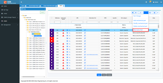
Select Altair-Demo-04 > MAIN > 2.0 in the BOM Tree and right-click and select Check In/Out > Check Out.
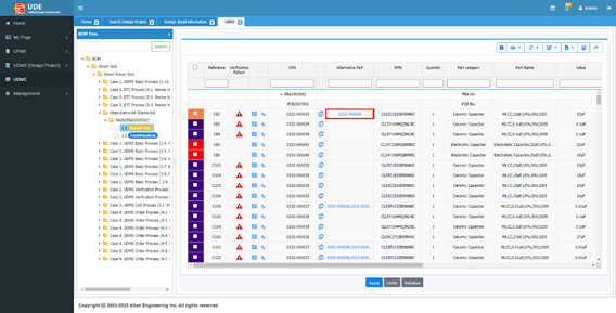
Enable the C82 part checkbox and select Edit > Alternative Part.
Figure 102.
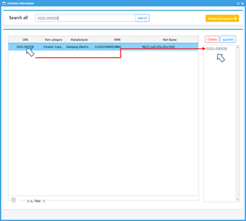
Search the 0202-000038 part and drag-and-drop
the part from the part list to the right box.
Figure 103.
After moving the alternative part, click
applied.
You can then find the alternative part is added to the part. Figure 104.
Click Apply.
Then the BOM is checked in automatically.
Export Excel File.
You can export the part list as an excel sheet to check and distribute. The
format of the exported excel is same with the part list page.
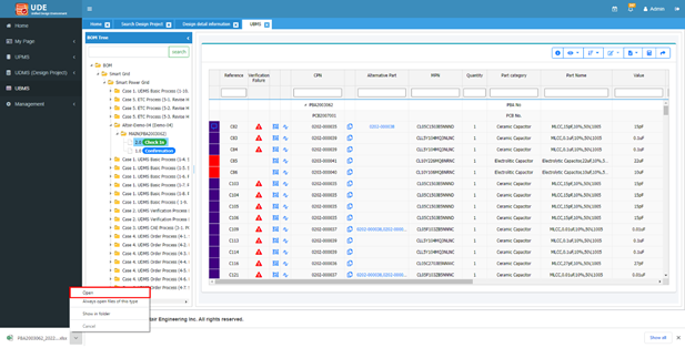
Select Export excel file > All to export all data.
Figure 105.
In the lower-left side, the excel is exported.
Click and select Open.
Figure 106.
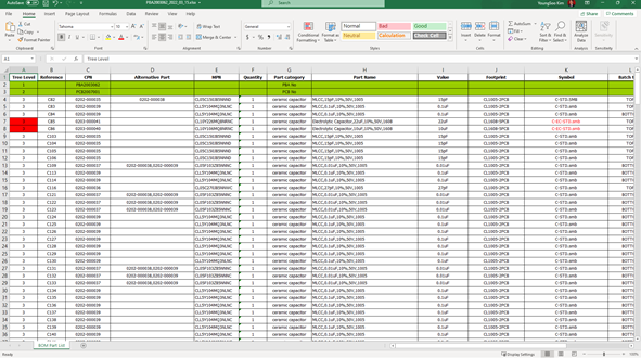
The exported excel is like below. Figure 107.
Unit price calculation.
By using the unit price calculation menu, you can estimate the total cost of
parts and this information can be exported to an excel as well.
Click Unit price calculation.
Figure 108.
You can see the unit prices and total price.
Part unit price is calculated based on the estimated price of the
part entered in the part information. In this design the price is
not accurate because some parts don’t have a unit price information.
But if an ERP system is linked with the UPMS, the price data becomes
more accurate.
Click Export excel file and open the exported
excel.
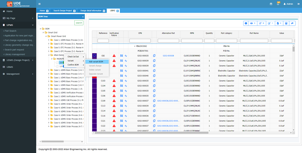
Edit Variant BOM.
When you proceed with a product design, the same product may be applied with
some parts changed depending on the destination. In such cases, you can apply
derivative parts to the same design drawing to create and manage BOMs for
multiple destinations.
Select Altair-Demo-04 > MAIN > 2.0, right-click, and select Variant > Add variant BOM.
Figure 109.
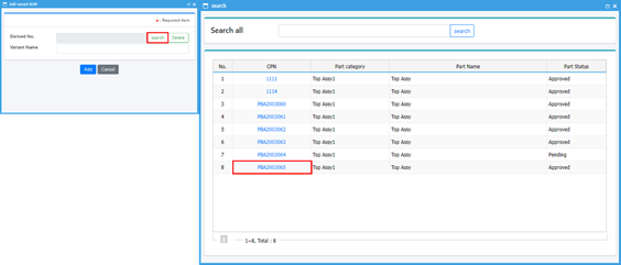
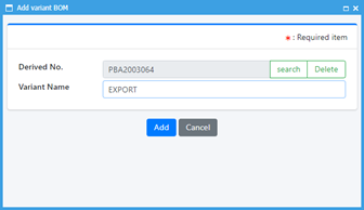
In the Add variant BOM dialog, select
search and select
PBA2003065 in the CPN column.
Figure 110.
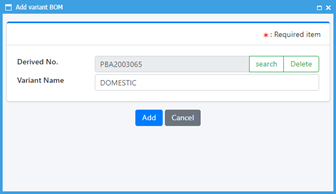
Change the Variant Name to DOMESTIC and click
Add.
Figure 111.
A new derived PCB assembly PBA2003065 is generated in the BOM
Tree. Figure 112.
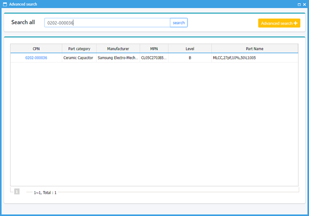
Enable the C82 part checkbox and select Edit > Part Change.
Figure 114.
Search and select 0202-000036 part.
Figure 115.
Click Apply.
Figure 116.
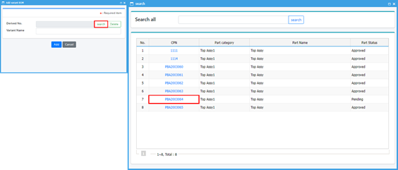
Select Altair-Demo-04 > MAIN > 2.0 in the BOM Tree, right-click, and select Variant > Add variant BOM.
Figure 117.
In the Add variant BOM dialog, select
search, and select the
PBA2003064 in the CPN column.
Figure 118.
Change the Variant Name to EXPORT and click
Add.
Figure 119.
A new derived PCB assembly PBA2003064 is generated in the BOM
Tree. Figure 120.
Select Altair-Demo-04 > MAIN > PBA2003064 > 2.0 in the BOM Tree, right-click, and select Check In/Out > Check Out.
Figure 121.
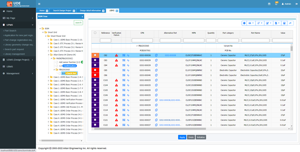
Enable the C82 part checkbox and select Edit > Part Change.
Figure 122.
Search and select 0202-000036 part and click
Apply.
Figure 123.
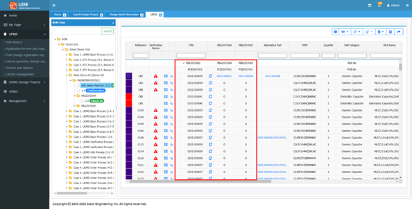
Select Altair-Demo-04 > MAIN > 2.0 to view the master and variant BOM.
In the BOM list, the o mark means the part is same with the master BOM
and part name means the part is different from the master BOM. Figure 124.
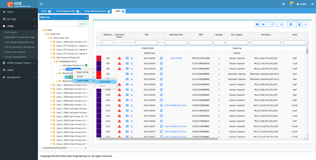
Select Altair-Demo-04 > MAIN > PBA2003064 > 2.0, right-click, and select Confirm BOM > Confirmation.
Figure 125.
Select Altair-Demo-04 > MAIN > PBA2003065 > 2.0, right-click, and select Confirm BOM > Confirmation.
Figure 126.
Select Altair-Demo-04 > MAIN > 2.0 and select Export excel file > All.
Figure 127.
Click the lower-left output to see the exported excel file.
You can see the full BOM list for all PBA.
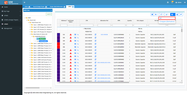
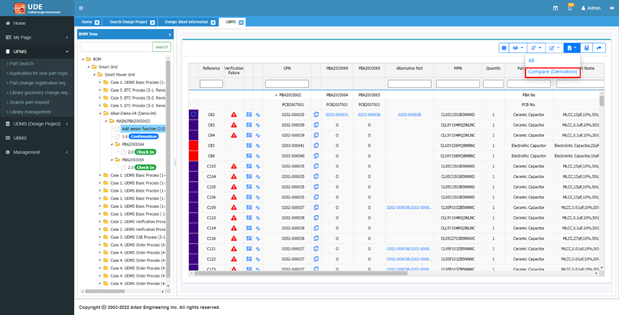
Close the excel file and select Export excel
file and select Compare
(Derivation).
Figure 128.
You can then see that only the changes to the master and
derivative models.
User Registration
There are two ways to register a user for UDE: administrator approves the account
after a user has applied for it and administrator creates the account.
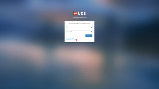
Request to register a new account.
Execute a web browser and connect to the UDE server.
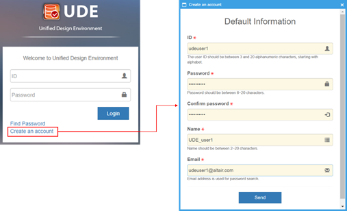
Click Create an account.
Figure 129.
For ID, enter udeuser1.
For Password, enter udeuser100.
Click send to apply for creating an
account.
Figure 130.
After requesting a new account, click
OK.
The request is sent to the administrator via e-mail, and if the
administrator finds out about the registration request, the
administrator can register the user account.
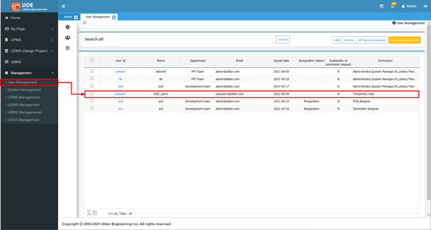
Select Management > User Management.
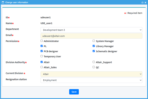
In the user list, locate the Temporary User and click the user
ID.
Figure 131.
In the Change user information dialog, specify the user information and
assign the user’s permission.
Click Save.
Figure 132.
After saving the user information, the user can login the UDE
system and approval message is sent to user via e-mail.
Logout and login using the created user information.
When you sign in to the UDE system, the Home screen
displays.
 .
.
 .
.


 in
the upper-right side to close all dialogs.
in
the upper-right side to close all dialogs.

 .
.

 to
view the schematic data using PollEx Logic.
to
view the schematic data using PollEx Logic.
 to
see the result.
to
see the result.
 to
execute PollEx Logic DFE.
For more information about PollEx Logic DFE, refer to the Logic DFE user guide.
to
execute PollEx Logic DFE.
For more information about PollEx Logic DFE, refer to the Logic DFE user guide.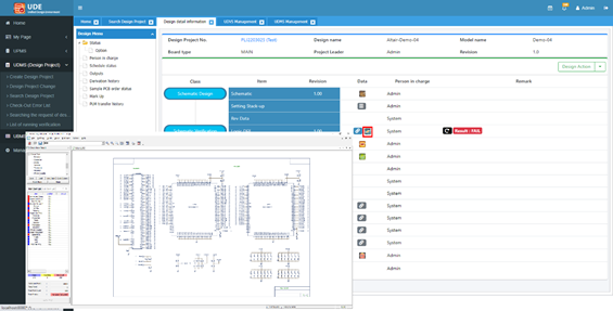
 to
view the part list data.
The part list will be shown as a BOM list format.
to
view the part list data.
The part list will be shown as a BOM list format.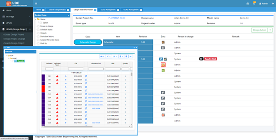
 to
set up the layer stack up.
to
set up the layer stack up.
 to
see the PCB design.
to
see the PCB design.
 of
PCB DFM to see more detail information using PollEx DFM.
of
PCB DFM to see more detail information using PollEx DFM.
 of
PCB DFM to see the DFM input settings.
of
PCB DFM to see the DFM input settings.

 of
PCB DFE to see more detail information using PollEx DFE.
of
PCB DFE to see more detail information using PollEx DFE.
 , and
you cannot click the icon. But you can check the detail information
using PollEx DFA.
, and
you cannot click the icon. But you can check the detail information
using PollEx DFA. to
see the detail information.
to
see the detail information.
 of
PCB DFE+ item to see the DFE verification result.
of
PCB DFE+ item to see the DFE verification result.
 of
PCB DFE+ to see more detail information using PollEx DFE+.
of
PCB DFE+ to see more detail information using PollEx DFE+.
 to
set up the allowable error.
to
set up the allowable error.

 of
PCB DFM.
of
PCB DFM.


 and
click the right button of mouse and select .
and
click the right button of mouse and select .
 of
Design Action and select Revise.
of
Design Action and select Revise.
 to
check the detail information.
to
check the detail information.
 and
select Sort by part number to change the view
mode.
and
select Sort by part number to change the view
mode.
 of
C82 reference to check the history.
of
C82 reference to check the history.