Automatic mode
1. User input parameters
| Label | Symbol | Tooltip, note, formula |
| Phase sequence | * | Phase sequence (all modes). |
| No. parallel paths | P paths | Number of parallel paths (all modes). |
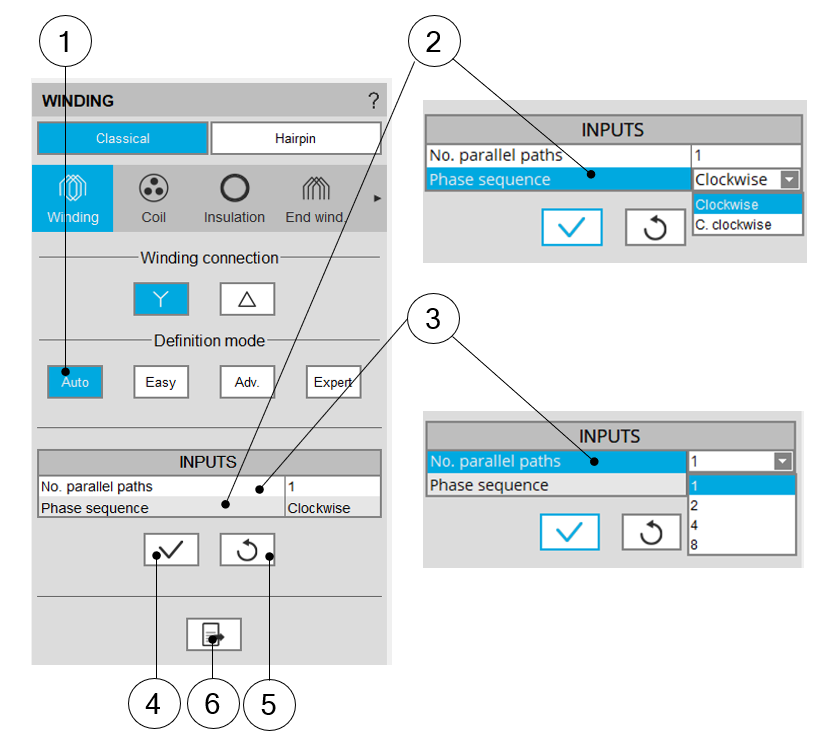
2. Building the winding architecture - Automatic mode – Main principles
 |
|
| Building the winding architecture - Automatic mode | |
| 1 | Selection of Automatic mode for building the winding architecture. |
| 2 | Definition of the phase sequence i.e. the rotation direction of the
Magneto-Motive Force (M.M.F): Clockwise or Counterclockwise (Clockwise or C. clockwise). The rotation direction is defined when facing the machine on the connection side. |
| 3 | Number of parallel paths. The possible numbers of parallel paths are automatically computed and proposed to the user. When the user chooses a number of parallel paths the connections on the winding scheme are automatically updated. See examples below. |
| 4 | Button to apply inputs. Pressing the enter key twice applies inputs too. |
| 5 | Button to restore default input values. Default values are those which define the winding architecture by using the automatic mode. |
| 6 | Icon to export winding data into a text file |
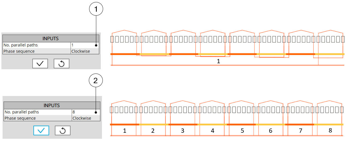
3. Parallel paths
 |
|
| Building the winding architecture – The number of parallel paths is represented in the winding scheme | |
| 1 | Example where the No. parallel paths is equal to 1. |
| 2 | Example where the No. parallel paths is equal to 8. |