 Package Modelica.Mechanics.MultiBody.Interfaces
Connectors and partial models for 3-dim. mechanical components
 Package Modelica.Mechanics.MultiBody.Interfaces
This package contains connectors and partial models (i.e., models that are only used to build other models) of the MultiBody library.
Extends from Modelica.Icons.InterfacesPackage (Icon for packages containing interfaces).
| Name | Description |
|---|---|
FlangeWithBearing | Connector consisting of 1-dim. rotational flange and its bearing frame |
FlangeWithBearingAdaptor | Adaptor to allow direct connections to the sub-connectors of FlangeWithBearing |
Frame | Coordinate system fixed to the component with one cut-force and cut-torque (no icon) |
Frame_a | Coordinate system fixed to the component with one cut-force and cut-torque (filled rectangular icon) |
Frame_b | Coordinate system fixed to the component with one cut-force and cut-torque (non-filled rectangular icon) |
Frame_resolve | Coordinate system fixed to the component used to express in which coordinate system a vector is resolved (non-filled rectangular icon) |
LineForceBase | Base model for line force elements |
PartialAbsoluteSensor | Base model to measure an absolute frame variable |
partialColorMap | Interface for a function returning a color map |
PartialElementaryJoint | Base model for elementary joints (has two frames + outer world + assert to guarantee that the joint is connected) |
PartialForce | Base model for force elements (provide frame_b.f and frame_b.t in subclasses) |
partialGravityAcceleration | Interface for the gravity function used in the World object |
PartialLineForce | Base model for massless line force elements |
PartialOneFrame_a | Base model for components providing one frame_a connector + outer world + assert to guarantee that the component is connected |
PartialOneFrame_b | Base model for components providing one frame_b connector + outer world + assert to guarantee that the component is connected |
PartialRelativeSensor | Base model to measure a relative variable between two frames |
partialSurfaceCharacteristic | Interface for a function returning surface characteristics |
PartialTwoFrames | Base model for components providing two frame connectors + outer world + assert to guarantee that the component is connected |
PartialTwoFramesDoubleSize | Base model for components providing two frame connectors + outer world + assert to guarantee that the component is connected (default icon size is factor 2 larger as usual) |
PartialVisualizer | Base model for visualizers (has a frame_a on the left side + outer world + assert to guarantee that the component is connected) |
ZeroPosition | Set absolute position vector of frame_resolve to a zero vector and the orientation object to a null rotation |
 Connector Modelica.Mechanics.MultiBody.Interfaces.Frame
Basic definition of a coordinate system that is fixed to a mechanical component. In the origin of the coordinate system the cut-force and the cut-torque is acting. This component has no icon definition and is only used by inheritance from frame connectors to define different icons.
| Type | Name | Description |
|---|---|---|
Position | r_0[3] | Position vector from world frame to the connector frame origin, resolved in world frame |
Orientation | R | Orientation object to rotate the world frame into the connector frame |
flow Force | f[3] | Cut-force resolved in connector frame |
flow Torque | t[3] | Cut-torque resolved in connector frame |
 Connector Modelica.Mechanics.MultiBody.Interfaces.Frame_a
Basic definition of a coordinate system that is fixed to a mechanical component. In the origin of the coordinate system the cut-force and the cut-torque is acting. This component has a filled rectangular icon.
Extends from Modelica.Mechanics.MultiBody.Interfaces.Frame (Coordinate system fixed to the component with one cut-force and cut-torque (no icon)).
| Type | Name | Description |
|---|---|---|
Position | r_0[3] | Position vector from world frame to the connector frame origin, resolved in world frame |
Orientation | R | Orientation object to rotate the world frame into the connector frame |
flow Force | f[3] | Cut-force resolved in connector frame |
flow Torque | t[3] | Cut-torque resolved in connector frame |
 Connector Modelica.Mechanics.MultiBody.Interfaces.Frame_b
Basic definition of a coordinate system that is fixed to a mechanical component. In the origin of the coordinate system the cut-force and the cut-torque is acting. This component has a non-filled rectangular icon.
Extends from Modelica.Mechanics.MultiBody.Interfaces.Frame (Coordinate system fixed to the component with one cut-force and cut-torque (no icon)).
| Type | Name | Description |
|---|---|---|
Position | r_0[3] | Position vector from world frame to the connector frame origin, resolved in world frame |
Orientation | R | Orientation object to rotate the world frame into the connector frame |
flow Force | f[3] | Cut-force resolved in connector frame |
flow Torque | t[3] | Cut-torque resolved in connector frame |
 Connector Modelica.Mechanics.MultiBody.Interfaces.Frame_resolve
Basic definition of a coordinate system that is fixed to a mechanical component. In the origin of the coordinate system the cut-force and the cut-torque is acting. This coordinate system is used to express in which coordinate system a vector is resolved. A component that uses a Frame_resolve connector has to set the cut-force and cut-torque of this frame to zero. When connecting from a Frame_resolve connector to another frame connector, by default the connecting line has line style "dotted". This component has a non-filled rectangular icon.
Extends from Modelica.Mechanics.MultiBody.Interfaces.Frame (Coordinate system fixed to the component with one cut-force and cut-torque (no icon)).
| Type | Name | Description |
|---|---|---|
Position | r_0[3] | Position vector from world frame to the connector frame origin, resolved in world frame |
Orientation | R | Orientation object to rotate the world frame into the connector frame |
flow Force | f[3] | Cut-force resolved in connector frame |
flow Torque | t[3] | Cut-torque resolved in connector frame |
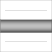 Connector Modelica.Mechanics.MultiBody.Interfaces.FlangeWithBearing
This hierarchical connector models a 1-dim. rotational flange connector and its optional bearing defined by a 3-dim. frame connector. If a connection to the subconnectors should be clearly visible, connect first an instance of FlangeWithBearingAdaptor to the FlangeWithBearing connector.
| Type | Name | Description |
|---|---|---|
parameter Boolean | includeBearingConnector | = true, if bearing frame connector is present, otherwise not present |
Flange_a | flange | 1-dim. rotational flange |
Frame | bearingFrame | 3-dim. frame in which the 1-dim. shaft is mounted |
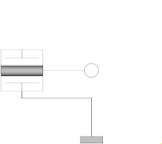 Model Modelica.Mechanics.MultiBody.Interfaces.FlangeWithBearingAdaptor
Adaptor object to make a more visible connection to the flange and frame subconnectors of a FlangeWithBearing connector.
| Type | Name | Default | Description |
|---|---|---|---|
Boolean | includeBearingConnector | false | = true, if bearing frame connector is present, otherwise not present |
| Type | Name | Description |
|---|---|---|
FlangeWithBearing | flangeAndFrame | Compound connector consisting of 1-dim. rotational flange and 3-dim. frame mounting |
Flange_b | flange | 1-dim. rotational flange |
Frame_a | frame | 3-dim. frame in which the 1-dim. shaft is mounted |
 Partial Model Modelica.Mechanics.MultiBody.Interfaces.PartialTwoFrames
This partial model provides two frame connectors, access to the world object and an assert to check that both frame connectors are connected. Therefore, inherit from this partial model if the two frame connectors are needed and if the two frame connectors should be connected for a correct model.
| Type | Name | Description |
|---|---|---|
Frame_a | frame_a | Coordinate system a fixed to the component with one cut-force and cut-torque |
Frame_b | frame_b | Coordinate system b fixed to the component with one cut-force and cut-torque |
 Partial Model Modelica.Mechanics.MultiBody.Interfaces.PartialTwoFramesDoubleSize
This partial model provides two frame connectors, access to the world object and an assert to check that both frame connectors are connected. Therefore, inherit from this partial model if the two frame connectors are needed and if the two frame connectors should be connected for a correct model.
When dragging "PartialTwoFrames", the default size is a factor of two larger as usual. This partial model is used by the Joint.Assemblies joint aggregation models.
| Type | Name | Description |
|---|---|---|
Frame_a | frame_a | Coordinate system fixed to the component with one cut-force and cut-torque |
Frame_b | frame_b | Coordinate system fixed to the component with one cut-force and cut-torque |
 Partial Model Modelica.Mechanics.MultiBody.Interfaces.PartialOneFrame_a
This partial model provides one frame_a connector, access to the world object and an assert to check that the frame_a connector is connected. Therefore, inherit from this partial model if the frame_a connector is needed and if this connector should be connected for a correct model.
| Type | Name | Description |
|---|---|---|
Frame_a | frame_a | Coordinate system fixed to the component with one cut-force and cut-torque |
 Partial Model Modelica.Mechanics.MultiBody.Interfaces.PartialOneFrame_b
This partial model provides one frame_b connector, access to the world object and an assert to check that the frame_b connector is connected. Therefore, inherit from this partial model if the frame_b connector is needed and if this connector should be connected for a correct model.
| Type | Name | Description |
|---|---|---|
Frame_b | frame_b | Coordinate system fixed to the component with one cut-force and cut-torque |
 Partial Model Modelica.Mechanics.MultiBody.Interfaces.PartialElementaryJoint
All elementary joints should inherit from this base model, i.e., joints that are directly defined by equations, provided they compute either the rotation object of frame_b from the rotation object of frame_a and from relative quantities (or vice versa), or there is a constraint equation between the rotation objects of the two frames. In other cases, a joint object should inherit from Interfaces.PartialTwoFrames (e.g., joint Spherical, because there is no constraint between the rotation objects of frame_a and frame_b or joint Cylindrical because it is not an elementary joint).
This partial model provides two frame connectors, a "Connections.branch" between frame_a and frame_b, access to the world object and an assert to check that both frame connectors are connected.
| Type | Name | Description |
|---|---|---|
Frame_a | frame_a | Coordinate system fixed to the joint with one cut-force and cut-torque |
Frame_b | frame_b | Coordinate system fixed to the joint with one cut-force and cut-torque |
 Partial Model Modelica.Mechanics.MultiBody.Interfaces.PartialForce
All 3-dimensional force and torque elements should be based on this superclass. This model defines frame_a and frame_b, computes the relative translation and rotation between the two frames and calculates the cut-force and cut-torque at frame_a by a force and torque balance from the cut-force and cut-torque at frame_b. As a result, in a subclass, only the relationship between the cut-force and cut-torque at frame_b has to be defined as a function of the following relative quantities:
  r_rel_b[3]: Position vector from origin of frame_a to origin
              of frame_b, resolved in frame_b
  R_rel     : Relative orientation object to rotate from frame_a to frame_b
Assume that force f = {100,0,0} should be applied on the body to which this force element is attached at frame_b, then the definition should be:
   model Constant_x_Force
      extends Modelica.Mechanics.MultiBody.Interfaces.PartialForce;
   equation
      frame_b.f = {-100, 0, 0};
      frame_b.t = zeros(3);
   end Constant_x_Force;
Note, that frame_b.f and frame_b.t are flow variables and therefore the negative value of frame_b.f and frame_b.t is acting at the part to which this force element is connected.
Extends from Modelica.Mechanics.MultiBody.Interfaces.PartialTwoFrames (Base model for components providing two frame connectors + outer world + assert to guarantee that the component is connected).
| Type | Name | Description |
|---|---|---|
Frame_a | frame_a | Coordinate system a fixed to the component with one cut-force and cut-torque |
Frame_b | frame_b | Coordinate system b fixed to the component with one cut-force and cut-torque |
 Partial Model Modelica.Mechanics.MultiBody.Interfaces.LineForceBase
All line force elements should be based on this base model. This model defines frame_a and frame_b and computes the (guarded) relative distance s. An assertion is raised if the relative distance length became smaller as parameter s_small.
Extends from Modelica.Mechanics.MultiBody.Interfaces.PartialTwoFrames (Base model for components providing two frame connectors + outer world + assert to guarantee that the component is connected).
| Type | Name | Default | Description |
|---|---|---|---|
Distance | s_small | 1e-10 | Prevent zero-division if distance between frame_a and frame_b is zero |
Boolean | fixedRotationAtFrame_a | false | =true, if rotation frame_a.R is fixed (to directly connect line forces) |
Boolean | fixedRotationAtFrame_b | false | =true, if rotation frame_b.R is fixed (to directly connect line forces) |
| Type | Name | Description |
|---|---|---|
Frame_a | frame_a | Coordinate system a fixed to the component with one cut-force and cut-torque |
Frame_b | frame_b | Coordinate system b fixed to the component with one cut-force and cut-torque |
 Partial Model Modelica.Mechanics.MultiBody.Interfaces.PartialLineForce
All massless line force elements should be based on this base model. This model defines frame_a and frame_b, computes the (guarded) relative distance s and provides the force and torque balance of the cut-forces and cut-torques at frame_a and frame_b, respectively. In sub-models, only the line force f, acting at frame_b on the line from frame_a to frame_b, as a function of the relative distance s and its derivative der(s) has to be defined. Example:
   model Spring
      parameter Real c "spring constant",
      parameter Real s_unstretched "unstretched spring length";
      extends Modelica.Mechanics.MultiBody.Interfaces.PartialLineForce;
   equation
      f = c*(s-s_unstretched);
   end Spring;
Extends from Modelica.Mechanics.MultiBody.Interfaces.LineForceBase (Base model for line force elements).
| Type | Name | Default | Description |
|---|---|---|---|
Distance | s_small | 1e-10 | Prevent zero-division if distance between frame_a and frame_b is zero |
Boolean | fixedRotationAtFrame_a | false | =true, if rotation frame_a.R is fixed (to directly connect line forces) |
Boolean | fixedRotationAtFrame_b | false | =true, if rotation frame_b.R is fixed (to directly connect line forces) |
| Type | Name | Description |
|---|---|---|
Frame_a | frame_a | Coordinate system a fixed to the component with one cut-force and cut-torque |
Frame_b | frame_b | Coordinate system b fixed to the component with one cut-force and cut-torque |
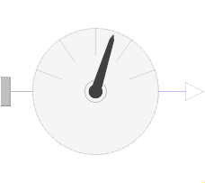 Partial Model Modelica.Mechanics.MultiBody.Interfaces.PartialAbsoluteSensor
This is the base class of a 3-dim. mechanics component with one frame and one output port in order to measure an absolute quantity in the frame connector and to provide the measured signal as output for further processing with the blocks of package Modelica.Blocks.
Extends from Modelica.Icons.RotationalSensor (Icon representing a round measurement device).
| Type | Name | Default | Description |
|---|---|---|---|
Integer | n_out | 1 | Number of output signals |
| Type | Name | Description |
|---|---|---|
Frame_a | frame_a | Coordinate system from which absolute quantities are provided as output signals |
output RealOutput | y[n_out] | Measured data as signal vector |
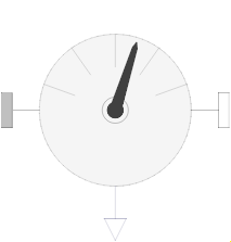 Partial Model Modelica.Mechanics.MultiBody.Interfaces.PartialRelativeSensor
This is a base class for 3-dim. mechanical components with two frames and one output port in order to measure relative quantities between the two frames or the cut-forces/torques in the frame and to provide the measured signals as output for further processing with the blocks of package Modelica.Blocks.
Extends from Modelica.Icons.RotationalSensor (Icon representing a round measurement device).
| Type | Name | Default | Description |
|---|---|---|---|
Integer | n_out | 1 | Number of output signals |
| Type | Name | Description |
|---|---|---|
Frame_a | frame_a | Coordinate system a |
Frame_b | frame_b | Coordinate system b |
output RealOutput | y[n_out] | Measured data as signal vector |
 Partial Model Modelica.Mechanics.MultiBody.Interfaces.PartialVisualizer
This partial model provides one frame_a connector, access to the world object and an assert to check that the frame_a connector is connected. It is used by inheritance from all visualizer objects.
| Type | Name | Description |
|---|---|---|
Frame_a | frame_a | Coordinate system in which visualization data is resolved |
 Model Modelica.Mechanics.MultiBody.Interfaces.ZeroPosition
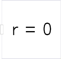
Element consisting of a frame (frame_resolve) that is fixed in the world frame and has it's position and orientation identical with the world, i.e. the position vector from origin of world frame to frame_resolve is zero vector and the relative orientation between those two frames is identity matrix.
This component provides no visualization.
Extends from Modelica.Blocks.Icons.Block (Basic graphical layout of input/output block).
| Type | Name | Description |
|---|---|---|
Frame_resolve | frame_resolve |
 Partial Function Modelica.Mechanics.MultiBody.Interfaces.partialGravityAcceleration
This partial function defines the interface to the gravity function used in the World object. All gravity field functions must inherit from this function. The input to the function is the absolute position vector of a point in the gravity field, whereas the output is the gravity acceleration at this point, resolved in the world frame.
Extends from Modelica.Icons.Function (Icon for functions).
| Type | Name | Description |
|---|---|---|
Position | r[3] | Position vector from world frame to actual point, resolved in world frame |
| Type | Name | Description |
|---|---|---|
Acceleration | gravity[3] | Gravity acceleration at position r, resolved in world frame |
 Partial Function Modelica.Mechanics.MultiBody.Interfaces.partialSurfaceCharacteristic
This partial function defines the interface of a function that returns surface characteristics for an object visualization, see e.g. Visualizers.Advanced.SurfaceCharacteristics.torus.
Extends from Modelica.Icons.Function (Icon for functions).
| Type | Name | Description |
|---|---|---|
Integer | nu | Number of points in u-Dimension |
Integer | nv | Number of points in v-Dimension |
Boolean | multiColoredSurface | = true: Color is defined for each surface point |
| Type | Name | Description |
|---|---|---|
Position | X[nu,nv] | [nu,nv] positions of points in x-Direction resolved in surface frame |
Position | Y[nu,nv] | [nu,nv] positions of points in y-Direction resolved in surface frame |
Position | Z[nu,nv] | [nu,nv] positions of points in z-Direction resolved in surface frame |
Real | C[if multiColoredSurface then nu else 0,if multiColoredSurface then nv else 0,3] | [nu,nv,3] Color array, defining the color for each surface point |
 Partial Function Modelica.Mechanics.MultiBody.Interfaces.partialColorMap
This partial function defines the interface of a function that returns a color map. Predefined color map functions are defined in package Modelica.Mechanics.MultiBody.Visualizers.Colors.ColorMaps.
Extends from Modelica.Icons.Function (Icon for functions).
| Type | Name | Description |
|---|---|---|
Integer | n_colors | Number of colors in the color map |
| Type | Name | Description |
|---|---|---|
Real | colorMap[n_colors,3] | Color map to map a scalar to a color |