Altair Flow Simulator 2022.2 Release Notes
Highlights
- Added grid for symbol placement in the modeling window.
- Disk Pumping element.
- Renamed the Advanced Orifice to Advanced Tube to better reflect its use cases.
New Features
- Grid for Symbol Placement
- A grid can be used for symbol placement when creating a flow and thermal
network. This helps make an evenly spaced network that looks better on
screen. The Activate Grid option must be selected for the symbols to
snap to the closest grid intersection. Hide the grid by selecting the
Show Grid option.Note: The location of the symbols does not affect the flow or thermal solution for most modeling methods (same as previous versions).
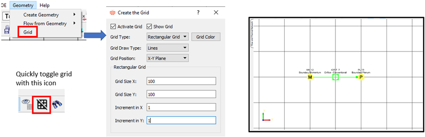
Figure 1. Grid for Symbol Placement - Disk Pumping Element
- Flow is entrained radially outward along a rotating disk. An element has
been added to simulate this affect. It can be used in the secondary air
systems of gas turbine engines.
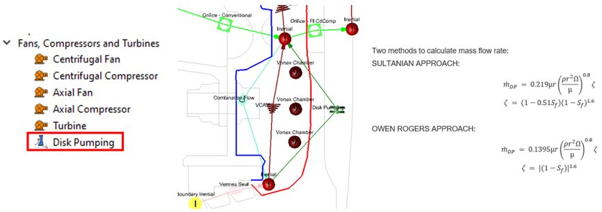
Figure 2. Disk Pumping Element - Tooth-By-Tooth Labyrinth Seal Element (BETA)
- A labyrinth seal element has been added that is like the Vermes Seal
element. The new element uses a tooth-by-tooth marching scheme to
calculate the pressure in each pocket using the seal flow rate and
calculated losses. The Vermes Seal element uses a global equation with
just the seal upstream pressure, downstream pressure, and losses to
calculate a flow rate. The Vermes Seal pocket pressures are estimated.
The new element is considered a BETA release until more testing is
completed.
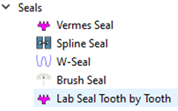
Figure 3.
Enhancements
- Heat Exchanger Rotation
- Generic and Plate-Fin Heat Exchanger can now be rotated to align the hot
(red) side and cold (blue) side with the appropriate elements.
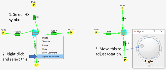
Figure 4. Adjust Heat Exchanger Rotation - Advanced Orifice Renamed Advanced Tube
- The Advanced Orifice was renamed Advanced Tube to better reflect its use
cases. The element is located under the Compressible Tubes instead of
the Orifices in the element library. The element itself has not changed
except for the new annulus input option. The Advanced Tube is used for
compressible gas applications and is similar to the standard
Compressible Tube. Advantages of the Advanced Tube over the standard
Compressible Tube include no limit on axial stations and the ability to
split the tube wall into different segments (like an inner surface and
outer surface of an annulus).
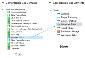
Figure 5. Renamed Advanced Orifice to Advanced Tube - Two Diameter Inputs for Tube Annulus
- The Compressible Tube, Advanced Tube, and Incompressible Tube now have
an inner and outer diameter input when the tube shape is an annulus. The
diameters can be constant, linear, and supplied for each station.
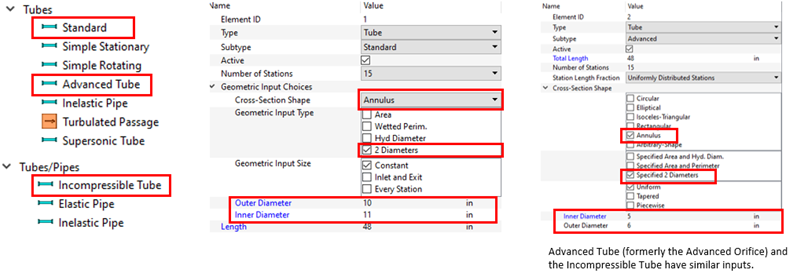
Figure 6. Input for the Two Diameters of an Annulus - Vermes Seal Improvements
- Three changes have been made to the Vermes Seal element to improve its
accuracy (comparison to test data).
- New option added for clearance factor (KFAC). The Bell-Bergelin
Advanced option was added to account for the tooth Reynolds
number (Re) not close to 10,000. The Tooth Re can be found in
the *.res file. Bell-Bergelin Advanced is
the default option for new elements, but old elements still use
the Bell-Bergelin Simple option.
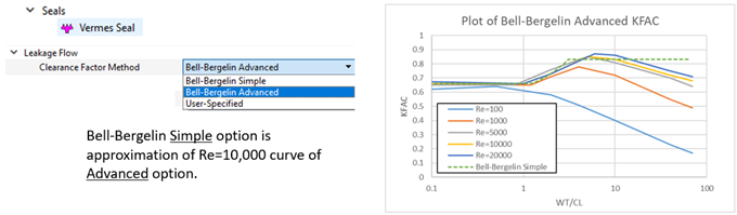
Figure 7. Clearance Factor Option - New option added for the honeycomb leakage multiplier (HCMULT)
for straight seals. The new option more accurately follows the
reference paper and is used automatically by old and new
elements.
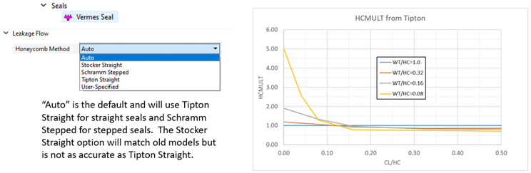
Figure 8. Honeycomb Multiplier Option - The mass flow for a choked seal has been modified. The seal mass
flow rate from the Vermes equation is now checked against a flow
rate from a choked flow calculation over the last tooth. The
choked flow rate is used if it is lower than the flow rate from
the Vermes equation. Also, the Cd used in the choked flow
calculation is no longer the same Cd as that used in the Vermes
equation.
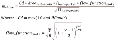
Figure 9.
- New option added for clearance factor (KFAC). The Bell-Bergelin
Advanced option was added to account for the tooth Reynolds
number (Re) not close to 10,000. The Tooth Re can be found in
the *.res file. Bell-Bergelin Advanced is
the default option for new elements, but old elements still use
the Bell-Bergelin Simple option.
- FI Cdcomp Element Added Equation Control
- The Cdcomp element calculates a discharge coefficient (Cd) based on
geometry and flow. There are six effects that go into this calculation.
These effects can be controlled with user input. The default options use
the same equations as previous versions. The new control allows you to
remove the effect, pick an alternate built-in equation, or use a custom
equation. Use the Customization Manager to create the custom equation in
either Python or Fortran.
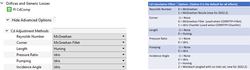
Figure 10. Cdcomp Equation Control - Display Options Window Update
- The Display Options window controls the text displayed in the modeling
window. This window has been modified to make it easier to use.
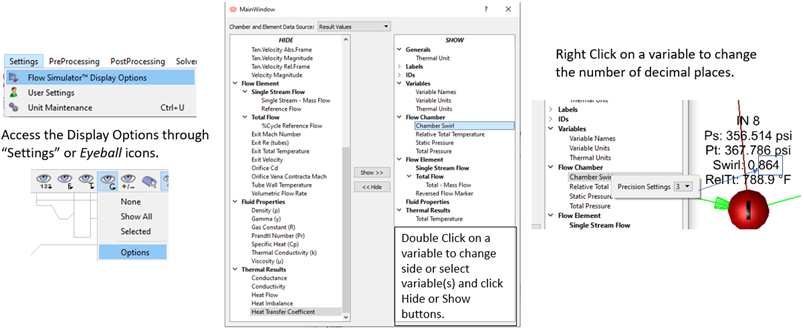
Figure 11. Display Options Update - Tube Centerline Coordinates
- The Compressible Tube, Advanced Tube, and Incompressible Tube elements
have a new input for coordinates of each tube station. These coordinates
facilitate the mapping of tube station data from Flow Simulator to other
solvers. The Flow Simulator coupling to other solvers is under
development and will be released in future versions. The station
coordinates are generated when a surface is selected for automatic
element creation. These coordinates are not used by the solver in this
release.
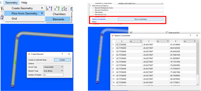
Figure 12. Tube Centerline Coordinates - PID Controller Transient Convergence Controls
- New controls added for convergence of PID controllers during a
transient. These controls determine what happens when all convergence
criteria are met except for the PID controller convergence criteria. It
is difficult to converge a PID controller to a tight criterion for all
timesteps. The PID controller may be lagging and need a few timesteps to
“catch-up” to the target value. These controls allow the solver to
continue to the next timestep, even if the controller is not converged.
These setting do not affect PID controllers used with steady-state
analysis.
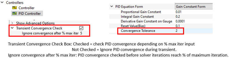
Figure 13. PID Convergence Control - Thermal Conductors and Nodes Using Liquids and Gasses
- This version allows thermal conductors and thermal nodes to use liquid
and gas properties as well as solids. This can be useful if a conductor
is used to represent a small air gap. Another application is a thermal
node representing an enclosed thermal volume of liquid (if the volume is
not enclosed, a fluid accumulator is a better choice).
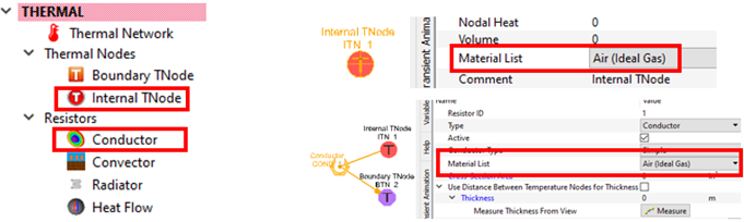
Figure 14. - Improvements to Element Creation Using Geometry
- Several improvements have been implemented to create elements directly
from geometry. This tool still works best for piping systems that use
tubes and bends. The improvements include setting element flow direction
based on the location of the surface selection (pick a surface near the
inlet end), and improved tube diameter extraction from the element
surface. Also, any element type can be created at a surface centerline
by pressing the Alt key while dragging the
element from the element library.
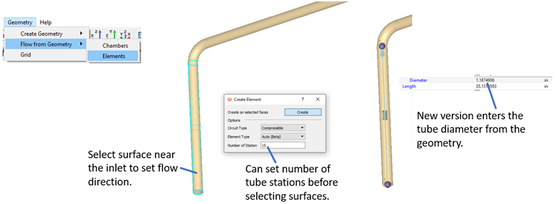
Figure 15. Element Creation Improvements - Boundary Chambers - New Options for Temperature, Swirl, and Quality
- New options to pass temperature, swirl, and fluid quality through a
boundary chamber have been added. These options can be used for closed
loop networks and for models with cavities on boundary inertial
chambers.
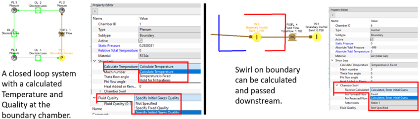
Figure 16. New Options for Temperature, Quality, and Swirl on Boundary Chambers - Reverse Element Direction with Space Bar
- Previous versions used a double-click on an element to reverse its direction. This was changed to avoid conflicts with other items using a double-click. In 2022.2, reverse an element's direction by pressing the space bar while selecting the element symbol.
- Element Arrow Size Control
- The element arrow size can be controlled under .
Known Issues
The following known issues will be addressed in a future release as we continuously
improve software performance:
- The new controller interface does not work with controllers that have two relations. For example, a 1D table and Python script in the same controller.
Resolved Issues
- Disappearing custom correlation inputs when renumbering an element.
- Orifice element radius changes to 0.0 after reversing element.
- Problem with some equations not working in the variable editor.
- Added some missing or incorrect items to the XML output file for cavity flows.
- Added detail to the plate-fin heat exchanger image in the Property Editor.