Defeaturing and transformation stages
Introduction
The second stage is a stage for defeaturing the geometry and for transforming the entities of the CAD context into entities of the Flux PEEC project.
Defeaturing of the geometry
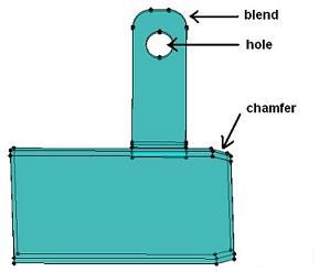
Within the CAD context, the user has the possibility to modify the imported geometry by removing the holes, the blends and the chamfers that are present on the geometric objects.
Moreover, the user can also cut the geometric objects into several objects by means of cut planes, in order that the novel entities comply with the criteria for the construction of the conductors ( unidirectional and bidirectional ).
The use of these different commands is presented in detail in the section " Context of CAD defeaturing ", whereas an example of principle is shown here below:
| modifications to make | final result |
|---|---|
|
example (IGES import):
The goal is to remove the hole, the two blends as well as the chamfers in order to next get a simpler to mesh geometry. |
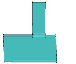
after modifications:
The hole has been filled, the blends and chamfers have been removed (transformed into right angles). The geometric object is now much simpler to mesh. |
Transformation of the entities
When the defeaturing stage is finished, the user has to quit the CAD context in order to carry on, in the standard working context of Flux PEEC, the preparation of the project to simulate.
This exit leads to the transformation of the entities of the CAD context into geometric entities appropriate to the Flux PEEC environment, i.e. of Point, Line, Face and Volume type.
The correspondences between the entities of the CAD context and the Flux PEEC geometric entities are summarized in the following table:
| CAD entity | Flux PEEC geometric entity |
|---|---|
| top | point |
| edge | line |
| face | face |
| geometric object | volume |

