MV-2021: Simulate an Automotive Door Closure Event
In this tutorial, you will learn how to create flexible and rigid body models and simulate a door closure.
- Use an FEM file to create a flexible body file.
- Use body data to create a rigid body model.
- Make the door flexible and use the flexbody file created in the model.
- Set up a door closure simulation.
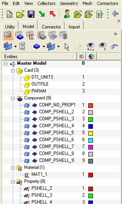
Review the Finite Element Model for the Flexible Door
In this step, you will review the contents of the finite element (FE) model, which is the starting point for creating a flexible body.
Generate the Flexbody using Flex Prep
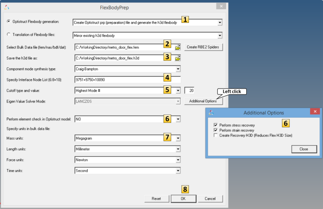
In this step, you will use the FEM file created in Step 1 and use Flex Prep to generate a flexible body H3D file. A pre-requisite for going through this step of the tutorial is an understanding of Flex Prep as described in MV-2010: Flexbody Generation using Flex Prep and OptiStruct.
Create the MBD Model of the Car Door
In this step, you will create the MBD model of the car door, after which the door closure simulation can be performed.
For this model, use the following units for length, mass, force, and time, respectively: millimeter, megagram, Newton, second.
Model Units
Points
For building this model, a total of six points need to be created.

Figure 4. Points Required for the Model
Bodies
In this model, there are two bodies: one body to represent the car and another to represent the flexible door.
Graphics
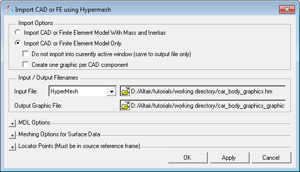
After Point 6 above, you can see that the Door Body has a graphical representation, but Car Body does not. You can add a file graphic to the Car Body so that visualization of the model becomes more meaningful.
Joints
For this body, you will need to add a total of four constraints/joints. One of these joints will need to be added using the XML template.
Initial Conditions
In this simulation, body initial velocity will act as the primary motion input to the model.
Markers
To represent the locking mechanism of the car door, you will use a sensor activated fixed joint between the Car Body and the Door Body that initially is deactivated. The fixed joint will need to be created using XML templates since the MotionView interface allows joints to be created using bodies and points. In this case, you need to create the joint between two initially non-coincident markers.
Sensors
In this model, you will use an Event Sensor to detect the closing of the door. At the instance of the event detection, the fixed joint between the door and the car body is activated to simulate the actual locking mechanism.
Templates
To simulate the door lock, you need a fixed joint between the door and the car body. The fixed joint needs to be activated with the sensor. The activation of the joint and the deactivation of the sensor can be done using a sequential simulation operation.


