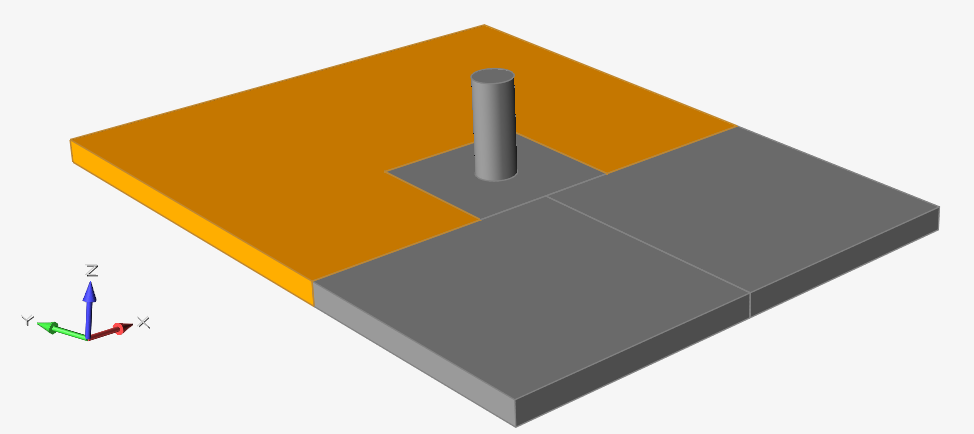
Tutorial: Inspire Friction Stir Welding Model Setup

Set up and complete a friction stir welding analysis and post-process the data.

In this tutorial you will learn about the Inspire Friction Stir Welding interface and how to:
  • Import die geometry
  • Set up an analysis for a simple butt joint.
  • Launch HyperXtrude solver to run friction stir welding analysis
  • Post process the results

Open the Tutorial Model

Data files are available in the tutorial_models folder in the installation directory in Program Files\Altair\2022\InspireExtrude2022.2\tutorial_models\fsw\tutorial-1\.

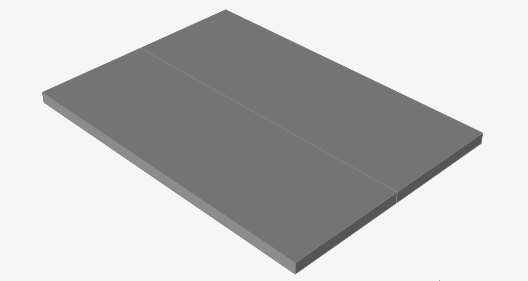
  1. 1. Open the butt-joint.x_t tutorial model file.


  2. 2. Set the display units to Metric (mm kg MPa C s).

Select Materials

  1. From the Friction Stir Welding ribbon, click the Materials tool.
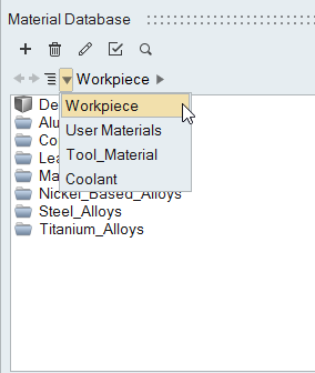
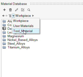
  2. In the Material Database dialog, to the right of , click the triangle and select Workpiece.


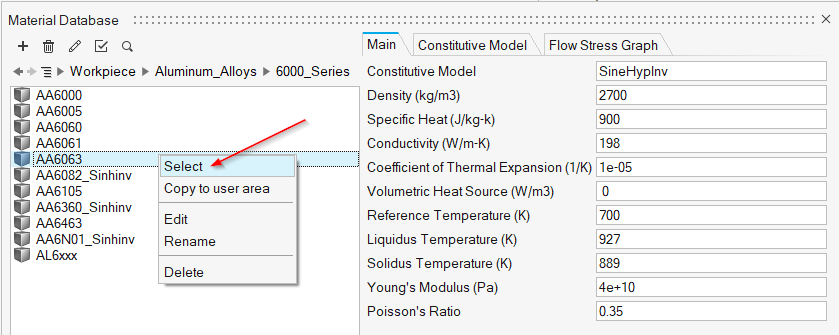
  3. 3. Select the workpiece material AA6063. Right-click on the material and select Select.


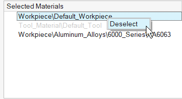
  4. Right-click on the Default_Workpiece material in the selected materials and click Deselect.


  5. To the right of , click the triangle and select Tool_Material.


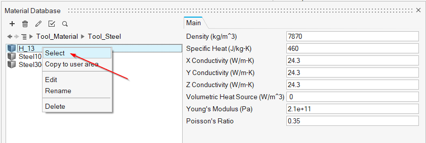
  6. Select the tool material H_13. Right-click on the material and select Select.


  7. Click OK to save and close the window.

Identify the Plates

  1. Click the Plates icon.

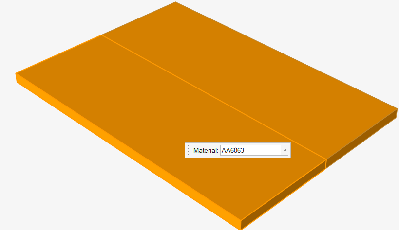
  2. Select both left and right plates in the model, and select the material AA6063 in the microdialog.


  3. Right-click and mouse through the check mark to exit, or double-right-click.

Orient the Model

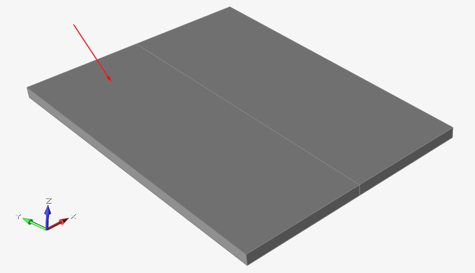
  1. Click the Orient icon.

  2. Select the top surface that will be pierced by the pin.


Create the Pin

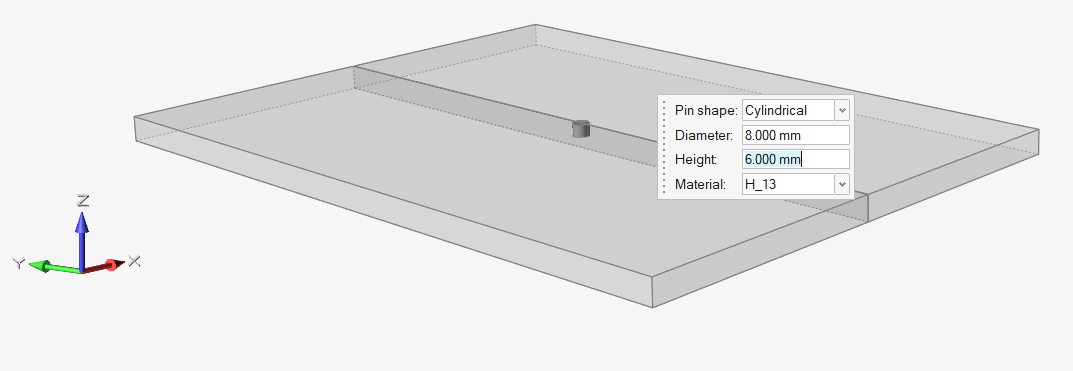
  1. Click the Pin icon.

  2. Modify the pin geometry and specify the pin material with the microdialog.


  3. Right-click and mouse through the check mark to exit, or double-right-click.

Create the Shoulder

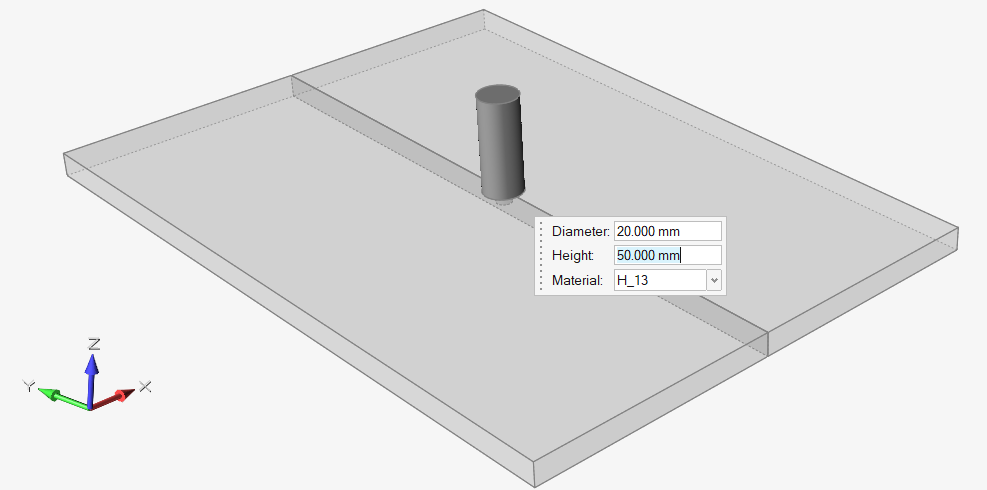
  1. Click the Shoulder icon.

  2. Modify the shoulder geometry and specify the pin material with the microdialog.


  3. Right-click and mouse through the check mark to exit, or double-right-click.

Create HAZ

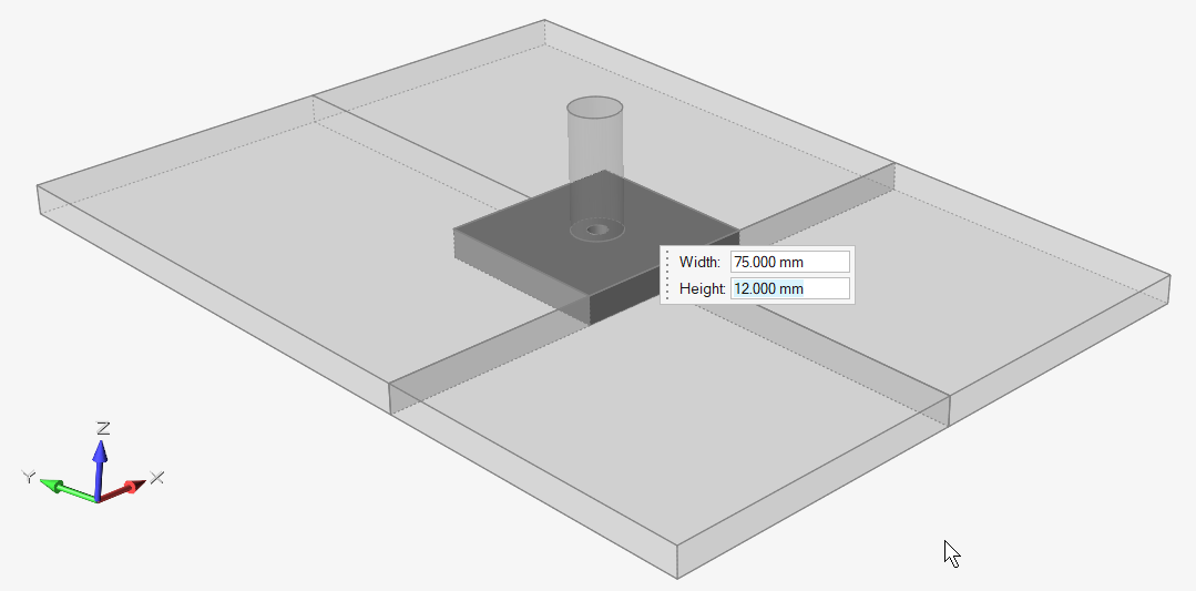
  1. Click the HAZ icon.

  2. Enter the HAZ dimensions in the microdialog.


  3. Right-click and mouse through the check mark to exit, or double-right-click.
HAZ and welded parts are created automatically.


Specify Process Parameters and Simulate

  1. Save the model.
  2. Click the Submit Job icon.

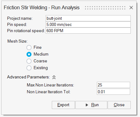
  3. Enter the analysis parameters.


    Note: To see Advanced Parameters options, you must have enabled it in Preferences.
  4. Click Run.

View Simulation Results

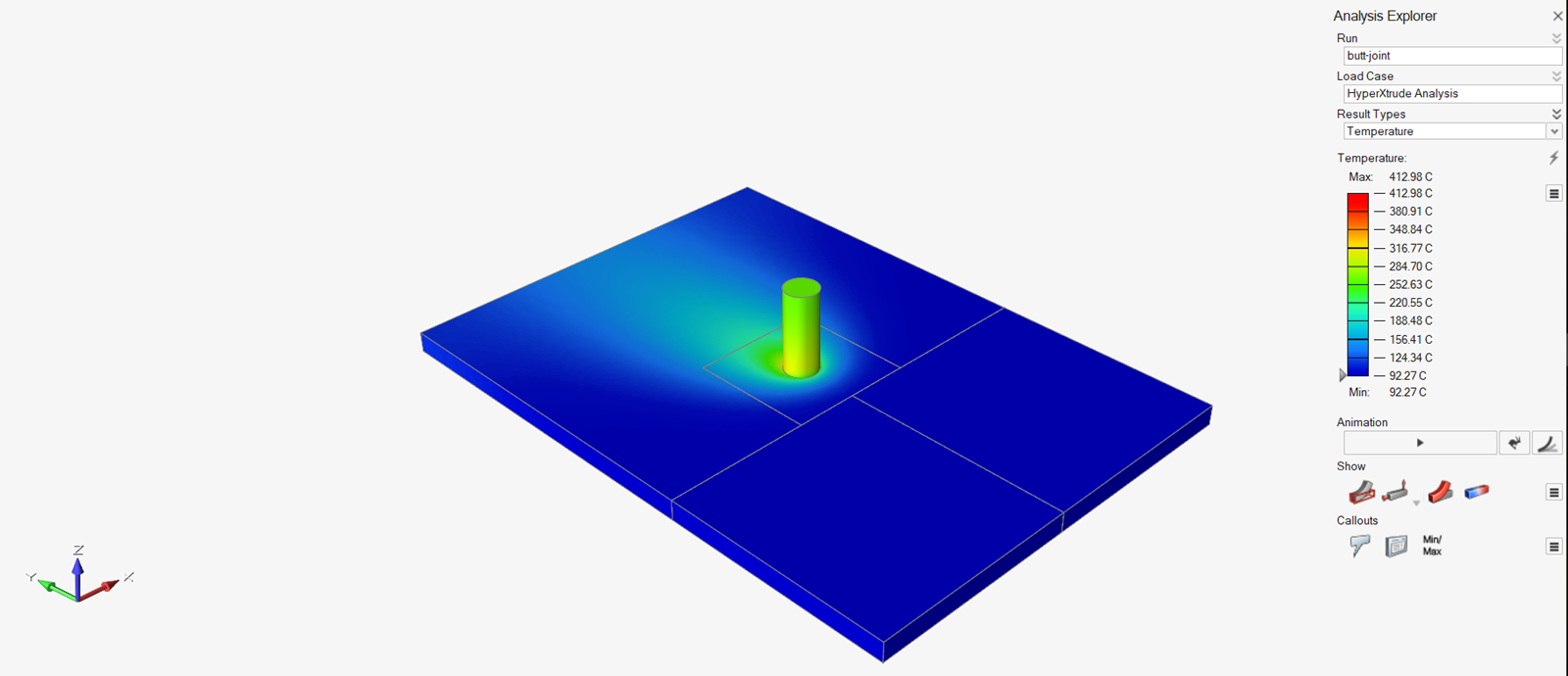
  1. When the analysis is complete, double-click the name of the run to open the results in the Analysis Explorer.
    Note: You can also open the butt-joint.ifsw file to view those same results.
  2. Select the Temperature result type.


  3. Click the Play button in the Animation ribbon.