Get Started with Inspire Cast
Walk through the five steps needed to define and run a casting analysis.
Specify the Cast Part
Specify the cast part, designate the filling system, and set the gravity direction.
Note: Before you begin, you'll need to import or create the
geometry of the cast part and the filling system. Refer to the section on parametric
modeling for more information about creating and modifying
geometry.
- Slect the Casting tab on the ribbon.
-
Select the Designate Casting Part
 tool, then select the part to be cast in the
modeling window.
tool, then select the part to be cast in the
modeling window.
-
Select the Designate Filling System
 tool, then select the filling
system parts in the modeling window.
tool, then select the filling
system parts in the modeling window.
-
Select the Set Gravity Direction
 tool, then use the options on
the microdialog to define the direction of gravity.
tool, then use the options on
the microdialog to define the direction of gravity.
Add Gates
Desigate an imported inlet surface as a gate, or create a virtual gate.
Note: If you only want to calculate the solidification analysis, you can skip adding
an inlet.
On the Gate icon, choose one of the following:
-
To designate an inlet surface as a gate, select the Designate Surfaces as Gates
 tool, then select the surface where the
predefined gate is located in the modeling window.
tool, then select the surface where the
predefined gate is located in the modeling window. - To create a virtual gate, select the Add/Edit
Gate
 tool, select a surface on the model to position
the center of the gate, then enter the gate's dimensions in the
microdialog.
tool, select a surface on the model to position
the center of the gate, then enter the gate's dimensions in the
microdialog.
Define Tooling Components
Simulate commonly used casting components.
-
Select the Components tool.

-
Select a tool to create or designate a part as that type of component.
- Select the Core tool, then click on one of the
red locations to add a core.
 Note: Double-click any surface to automatically select adjacent surfaces with an adjoining angle less than or equal to the Tolerance Angle defined under Selection Options on the guide bar.
 - Select the Chiller tool, then select a surface to
add a chiller.

- Select the Riser tool, then select a surface to
add a riser. A lateral or top riser is created, depending on the orientation
of the surface with respect to the direction of gravity.

- Select the Sleeve tool, then select a riser to
add a sleeve around it.

- Select the Overflow tool, then select a surface
to add an overflow.

- Select the Mold tool to add a mold. If you don't
create a mold using this tool, a mold is automatically created when you run
a casting analysis.

- Select the Cooler tool to add a cooler, then
sketch the path of the cooling line by clicking on the model. The points
defining the path must be positioned on a single surface. Right-click to end
the path.

- Select the Filter tool, then click any point on
the filling systems to add a filter.

- Select the Shot Sleeve tool, then click the
cookie on the running system to create the shot sleeve. If there is no
cookie, it will be created automatically.

- Select the Crucible tool, then click any point on
the part or the filling system to create a crucible. Note that if you have
defined a gate, you must remove it to create a crucible.

- Select the Core tool, then click on one of the
red locations to add a core.
Specify Process Parameters
Select a casting process and specify its parameters, or perform a quick, general simulation with minimal input.
- Click the Basic Setup icon and enter the Initial Velocity or Filling Time to perform a quick casting analysis.
-
Alternatively, click
 and select Gravity,
High Pressure, or Low Pressure
to enter more detailed parameters specific to those processes.
and select Gravity,
High Pressure, or Low Pressure
to enter more detailed parameters specific to those processes.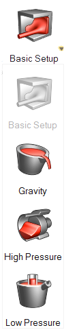
Run a Casting Analysis
Run a casting simulation and review the results.
-
Click Analyze
 on the Run icon.
- Select which types of analysis to run, then click Run.
- When the analysis is complete, click the green flag above the Run icon or select the run name in the Run Status window to review the results in the Analysis Explorer.