Export of AERO entity for OS and Nastran solver formats has been fixed.
RMB on sensor entity from the Browser for Crash and Ansys solver profiles
showing "Edit MONPNT" has been resolved.
Crash when MONPNT2 entity was wrongly defined with invalid elements has been
resolved.
Issue with RMB on some load collector type entities indicating "Create"
twice has been resolved.
F1 help for "Flutter curve plot" has been fixed.
Browsers
New Features
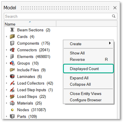
Displayed Entities Count
A Displayed Count context menu option has been added in the Model
Browser to check the count of displayed entities. Figure 1.
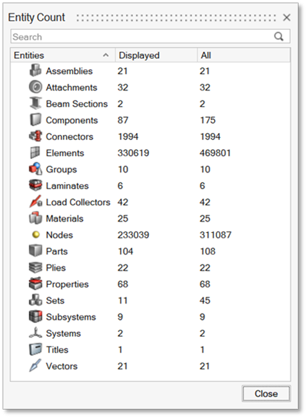
Selecting Displayed Count from the context
menu opens the Entity Count dialog, which provides
the displayed entity count for all the entities that are displayed in
the graphics (directly or indirectly). An optional All column can be
enabled to display the full count of entities. Figure 2.
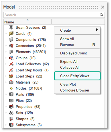
Option to Close All Entity Views
A Close Entity Views context menu option has been added in the Model
Browser to close all the entity-specific (flat) views at once. Figure 3.
Option to Delete All Free/Preserved Nodes from the Model Browser
All Free and Preserved nodes in the model can now be deleted using the
context menu options from the Nodes folder in the Model Browser. Figure 4.
Enhancements
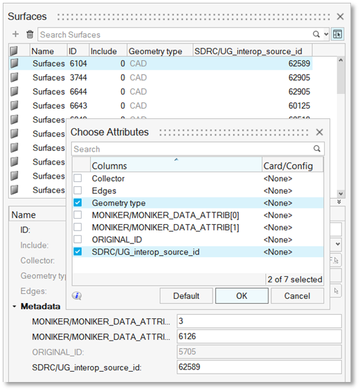
Attribute Columns for Geometric Entities
Any attribute including metadata can now be added as a column in the
Points, Lines, Surfaces, and Solids entity views using the
Choose Attributes dialog or the Add column
option from EE. Figure 5.
Element Configs in Choose Attribute Dialog
Element config types are now shown in the Card/Config column in the
Choose Attribute dialog. Figure 6.
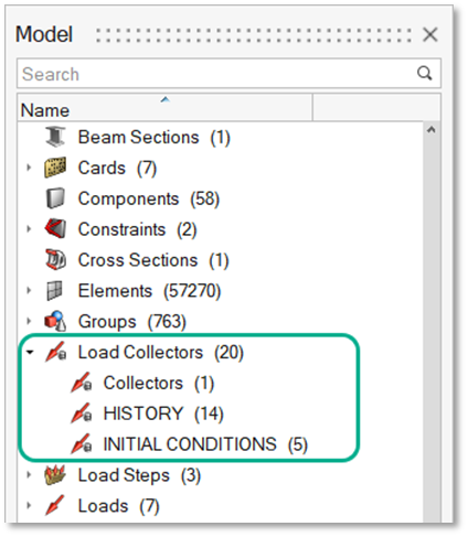
Sub-Categories for Load Collectors in Abaqus Interface
Load collectors are now organized into sub-categories in the Model
Browser under the Abaqus interface, to help in quick review. Figure 7.
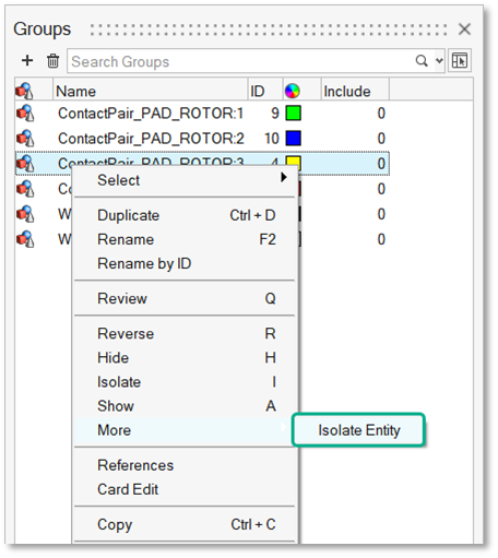
Isolate Entity Option in Browsers
An Isolate Entity context menu option has been added in browsers. It can
be used to isolate within the selected entity type leaving the display
state of all other entity types as it is. Figure 8.
Option to Create Tags from Model Browser
Tags can now be created using the Model Browser context menu Create
options.
Added O Shortcut for Organize
The Organize tool can now be invoked using the O keyboard shortcut after
selecting an entity in the browser.
Known Issues
The Entity Editor is not cleared when an entity is removed from the filtered
browser list.
The Keyword list for Create menu is removed from entity views upon loading a
model.
Resolved Issues
A performance issue while showing data in EE for load steps with multiple
references has been resolved.
A performance issue with opening Elements and Nodes Browsers has been
resolved.
A performance issue with invoking the context menu from the Loads folder in
the Model Browser has been resolved.
An issue with element type for RBE2 in attribute columns has been
resolved.
Certification
Enhancements
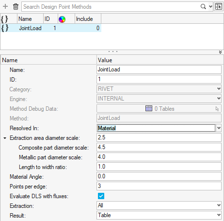
JointLoad method for fastener force extraction
A new Resolved In option to extract forces in various systems is now available.
Material system (default)
Elemental system
User system
Figure 9.
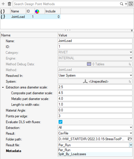
An option to directly write a *.csv file instead of
creating a table in session was added in 2022.1. To improve performances
with large number of loadcase, a new option to split the
*.csv file every N loadcases has been
introduced in this release. Figure 10.
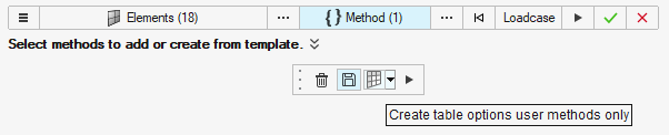
Run user method options
The ability to create an output table per run or per loadcases is now
available.
An option to keep method inputs in an output table is now exposed in a
microdialog. Figure 11.
Resolved Issues
Crash when creating marker shape (on Contour) using entity as nodeid is now
resolved.
Contouring result from large table (millions of rows) led to memory issue or
took hours. To improve memory footprint, his issue is resolved in this
release while contouring.
To improve memory footprint, API *filtertable performance has been improved
when flag allcolumns=0 is used.
Composites
New Features
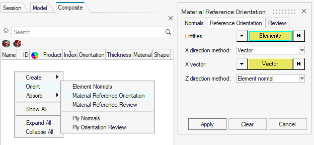
Material Reference Orientation Dialog
Panel material orientation functionality has been migrated to the
Material Reference Orientation dialog. It can
be accessed from the context menu of the Composite Browser. There are
three tabs:
Normals: to set shell element normals, which determine the
laminate stacking direction.
Reference Orientation: to set material reference orientation.
All methods from the previous Aerospace Material
Orientation dialog and panels are provided.
Review: to review material reference orientation vectors.
Supported solvers:
OptiStruct
Radioss
Abaqus
Ansys
LS-DYNA
Nastran
Figure 12.
Known Issues
Ply Stacking Performance on Large Models
If a large laminate is fully defined with a template property and plies
which all have an assigned shape, performance while manipulating the
stacking sequence by adding or removing plies or changing ply shapes may
be slow. As a workaround, a ply with no assigned shape can be
temporarily placed in the laminate and removed at the end of the
stacking process.
Connectors
New Features
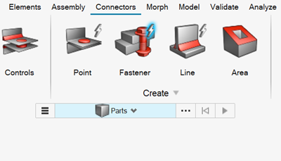
Auto Fastener Connector
An Auto Fastener tool has been added to pair holes and create connectors
to join them. Figure 13.
Enhancements
Line Connector Enhancements
Use the Imprint tool in the Connectors ribbon to imprint nodes as
significant points to a line connector.
A Non Linear distribution option was added for significant points.
An option to remove significant points from connector was added.
A Skip Welding option was added to all realizations.
Connector Control Enhancements
Element type can now be set from CC or EE for standard realizations (for
example, rigid, rod, and so on).
An option was added to increase the RBE3 radius for any type.
Control attributes are now dynamically added as a function of the Style
Number and Type from the feconfig.
hm_ce_getallfe has been enhanced to allow for easier development of
Customization Scripts.
Subsystem Hierarchy for Connectors
Following the changes made to the hierarchy of subsystems, connector
subsystems are assigned to the common parent subsystem of the
connector's links.
Eline Enhancements
Impulse can now be specified with up to 3 decimal points.
Aerospace Realizations
The None option was added for Auxiliary points in RBE3-CBUSH-RBE3.
Miscellaneous Enhancements
Added support for joint elements in the feconfig
file by using the joint keyword.
Beam sections with the necessary attributes are now created instead of
passing the attributes directly to the properties.
The RBE3 tool was added to the Connector ribbon.
Seam Quad LTB is now the default absorption config.
An option was added to apply the element's direction as a vector during
absorption.
An option was added to only display connectors/attachments linked to a
specific part.
Design Explorer
New Features
Property Design Variables
A new type of design variable has been added where you can select
elements or components in the model and allow their property assignment
to become a variable within explorations. For example, you can choose a
set of 1D elements and allow their section definition to be a
variable.
Design Variable Link Equations
Design variable links have previously been limited to linking one or
more variables to a main variable, ensuring that the linked variables’
value will be equal to the main value throughout the exploration. Now
you can link variables using equations or combinations of variables. For
example, a link could be created like variable3 = (variable1 +
variable2/2).
Generic Response
The new Generic Response can be used to create responses based on a
chosen reference solver output file. The enhancement allows you to
potentially create responses which are not amongst the current set of
out-of-the-box responses supported by Design Explorer.
Run Nominal Run Only
It is now possible to set up a DOE and run only its nominal run, which
can be useful to check and debug the model or exploration prior to fully
submitting the DOE for evaluation. To run only a nominal run, set the
DOE Type to MELS and set the number of runs to 0.
Apply Design Variables to Model
Selecting this new option in the Results Explorer Summary Table will
apply all design variable values for the selected run on the model.
Clustering Enhancements
Clustering uses unsupervised machine learning to group exploration
results according to user-specified criteria. Prior releases have
exposed limited clustering features in the Results Explorer Scatter Plot
tool. The updates to clustering include moving it to its own tool in the
Results Explorer, where you can now cluster based on load case and
result type of their choice. New enhanced visualization tools are
available, including the ability to visualize/animate all clusters,
overlay results for individual clusters, and create classifications,
which will be used via supervised machine learning in coming
releases.
Restriction: Currently, clustering is only
supported on Windows.
Design Space
New Features
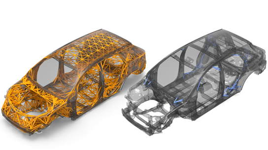
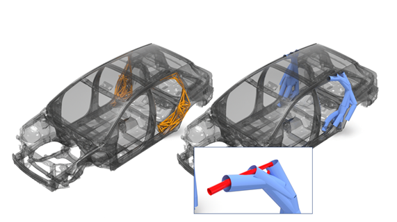
Exoskeleton Workflow
Exoskeleton is a workflow that enables and promotes design exploration
of both early concepts and mature structures. The workflow provides
insight as to how the structure may need reinforcing to meet a
predetermined performance criteria. Two optimization approaches are
supported: Topology and Size. Both approaches use 1D elements tied to
the structure. Figure 14. Topology Figure 15. Size
Extensions
New Features
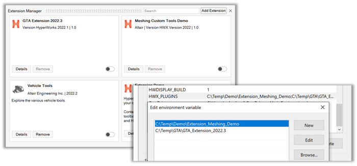
Pre-Defined Registration of Multiple Extensions Via an Environment
Variable
To start HyperWorks with a pre-defined set of extensions, you can now
set the environment variable HWX_PLUGINS to add one
or more directories from which all extensions will be registered. Click
Remove to disable these extensions. Figure 16.
Enhancements
Block the Disabling of Extensions
The Remove button can be disabled by adding the removable keyword,
<entry name="removable" value="true"/>, in the
general section of the extension.xml file.
Improved Error Messages
Meaningful error messages are displayed and the extension is not loaded
when a ribbon xml is not referenced from inside a profile in the
extension.xml file or when tags are not
matching.
Resolved Issues
The issue with ribbons and toolbars of some extensions not disappearing
after an extension has been disabled has been resolved.
Known Issues
The following known issues will be addressed in a future release as we continuously
improve performance of the software:
Loading extensions covering pre and post-profiles with the HyperMesh profile
active will not show the extension loaded in the post clients. The extension
needs to be enabled in at least one of the post clients. Similarly, the
extension needs to be loaded in the HyperMesh profile if it was loaded first
in one of the post profiles.
General
New Features
Multi-Model
It is now possible to have multiple HyperMesh pre-processing windows
active within the session, each with its own model. This removes the
need to have multiple copies of the application open and reduces memory
overhead.
Window and page management:
Up to 16 windows per page are supported. Multiple pages are also
supported. The organization of all the windows and pages can be
saved to a session file.
Model sync:
The model view can be synced between windows. If there are two
windows side by side and you rotate and/or zoom the model in the
first window, the model in the second window will move in
unison.
Copy and paste:
Entities can be selected for copy in one window and then pasted
into the model of another window. This works with most entity
types. Selection for copy can happen graphically or through the
browser.
The follow categories of entities are supported:
Physical entities, such as: Elements, Surfaces, and
Lines
Named entities such as: Parts, Materials, Properties,
LoadCollectors, and Optimization Entities
Non-named entities, such as: Loads and Vectors
Miscellaneous
A Copy IDs option has been added to the context menu under More > Copy IDs. This will copy the ID range to the clipboard.
Where applicable, common preferences will now adjust multiple HyperWorks
applications at once.
A global numeric precision can be set in Preferences > HyperMesh > Appearance > Numeric Format which will affect most dialogs and microdialogs with
floating point numbers.
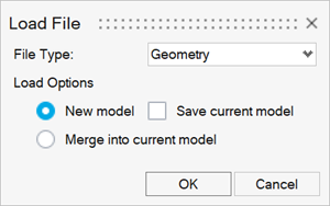
Drag/Drop
A dialog now opens when you drag-and-drop a file into HyperMesh. You can
open or import any file type using this method. Multi-model loading is
not supported. Figure 17.
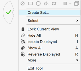
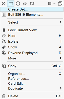
Create Set
The Create Set option has been added to the context menu for Nodes &
Element selection in OptiStruct, Radioss, Abaqus, ADVC, LS-DYNA, and
Permas. This is supported in idle and the Organize tool.
Figure 18.
Figure 19.
Find Tool
The Find tool is now available in the View Toolbar. Use the Find tool to
find and display other entities based on their connectivity or proximity
to the selected entities. Choose between the Attached to, Nearby, and
Shared by functions. Figure 20.
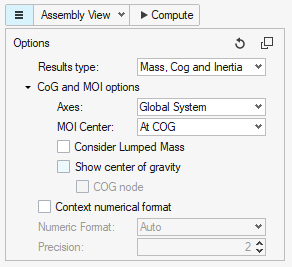
Mass Validation Tool
The Mass Validation Tool has been enhanced with following new
functionalities available from the hamburger menu: Figure 21.
Option for COG and MOI calculation in user defined coordinate
system.
Option for MOI calculation around selected coordinate system
center.
Option for the consideration of Lumped Mass in COG and MOI
calculation (only in LS-DYNA and Radioss profiles).
Options to show the calculated COG on the graphic and create a
Node at the COG location.
Option to change the numerical format and precision of the
values exposed in the GUI.
Enhancements
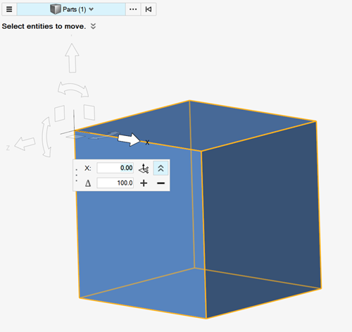
Move Tool
Orient the selected direction using the Vector tool. Hold
Ctrl and select three points to
define the direction by plane.
Use the + / - buttons to apply an incremental translation or
rotation in the selected direction.
The vector magnitude is automatically input as the increment for
translations.
Figure 22.
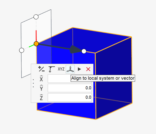
Vector Tool
Select a Vector entity to align to, or assign a local coordinate
System. Figure 23.
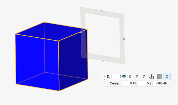
Plane Tool
Input the Plane center coordinates in the manipulator microdialog. Figure 24.
Known Issues
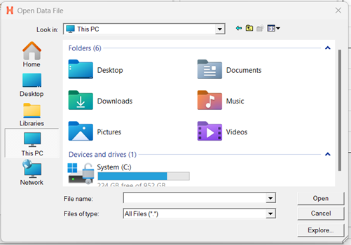
Known issues for the File
Open/Save dialogs and Message boxes:
There are inconsistencies in the appearance of the File
Open and File Save dialogs and
Message boxes.
Based on how they are opened and the available file extension
filters in the File Open and
Save dialogs, the appearance/style of the
dialog can differ from other instances.
Some of these dialogs can move behind the main application when
clicking elsewhere in the application. This requires you to bring
them to the foreground or reposition the application.
Figure 25 and Figure 26 show examples of different versions of the
File Open dialog: Figure 25. Figure 26.
HyperWorks can hang on re-launch in following instances: if the license is
close to expiring, when the license expiration warning dialog opens, and if
a non-default browser was active on shutdown.
To avoid this, one of the following environment variables can be
used:
ALM_NO_EXPIRE_WARNING: Disables the expiration warning.
ALM_EXPIRE_DAY_WARNING: Specifies the number of days before
license expiration, the warning message is given (default is
30).
If one of the environment variables listed above is not used to
avoid this issue and the issue occurs, deleting the settings files
will resolve the issue.
In some cases involving multi-monitor setups, if a browser or dialog is
dragged from one monitor to another, associated context menus can appear
outside the browser/dialog, potentially even on the original monitor.
When running in a NICE/DCV environment, there are drawing issues with the HWx
toolbelt.
On Linux, an error can be seen when importing/opening files from a directory
with a name/path containing non-ASCII characters. This error can be avoided
by using the encoding system utf-8 command, either in a
script or by manually typing it into the Tcl console, before
importing/opening the file(s).
Resolved Issues
Issues involving some dialogs (Parameter/Criteria
Editor, Advanced Selection dialog, and
so on) not being visible in certain multi-monitor configurations have been
resolved.
Performance issues associated with show, hide, and isolate have been
resolved.
Crash associated with importing an HyperMesh model on top of an existing
model has been resolved.
Performance issue while opening and switching ribbons has been
resolved.
Performance issue with invoking the graphics context menu for large models
has been resolved.
Optionally turn off Move Tool preview to improve the performance with large
models.
Geometry
New Features
Create Ribs Tool
The Create Ribs tool has been added under the Geometry Create pull-down
menu.
Find Symmetry Tool
The Find Symmetry tool has been added under the Geometry Cleanup
pull-down menu.
Arc Line Creation Tool
The Arc Line Creation tool has been added under Geometry - Shapes.
Enhancements
Free (Temp) Nodes and Preserve Nodes Functionality
Free (temp) nodes and preserve nodes functionality has been added under
the Nodes/Points Create tool.
New Create Mesh Option
A create mesh option for surface patch/ruled/drag/spin to create
geometry with mesh was added.
Parametric Creation
ParamFree etric creation of nodes and interpolate nodes functionality
was added under the Nodes/Point Create tool.
Parametric Line Creation
Parametric line creation was added under the Lines tool.
Matrix Browser
Resolved Issues
System selection is now considered correctly when querying results through
Matrix.
An issue with application crashes when referencing columns with labels
containing special characters in the equation definition has been
resolved.
Meshing
New Features
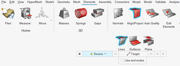
Align/Project Tool
The Align/Project tool has been added in the Elements ribbon. Figure 27.
Beam Section Contexts
New beam section contexts have been added in the Mesh Page for all
solver profiles.
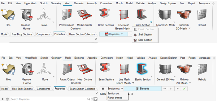
The 1D > HyperBeam panel has been removed. Instead, each solver profile,
except OptiStruct and Nastran, have new options in the Mesh ribbon to
create beam sections of Shell, Solid, or Elastic type from model data.
This can be done by selecting in-plane or by creating a section cut in
the model. Figure 28.
Shrink Wrap
Shrink wrap has been added under Mesh > 2D Mesh pull-down menu.
Acoustic Cavity
Acoustic Cavity has been added under Mesh > 3D mesh pull-down menu.
SPH
SPH has been added under Mesh > 2D mesh pull-down menu.
Enhancements
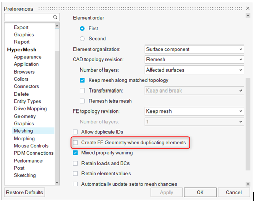
FE Geometry Creation on Duplicating Elements
If copied elements are orphan mesh, the output is orphan mesh.
If copied elements are FE geometry, the output is FE geometry.
If copied elements are associated to CAD geometry, the output depends on
the preferences:
If Create FE Geometry when duplicating elements is On, the
output is FE geometry.
If Create FE Geometry when duplicating elements is Off, the
output is Orphan mesh.
Figure 29.
Edit Element Tools
Significant performance improvements have been made for Edit element
tools.
QI Color Mode is Optional
QI color mode has been made optional. The default is OFF for all Edit
element tools.
Edit Elements Split Tool
Edit Elements Split tool supports standalone 1D splitting.
Resolved Issues
1D Stiffener meshing for Marine applications: generation of 1D stiffener
mesh from orphan lines is up to 30x faster on large ship models.
Model Build
New Features
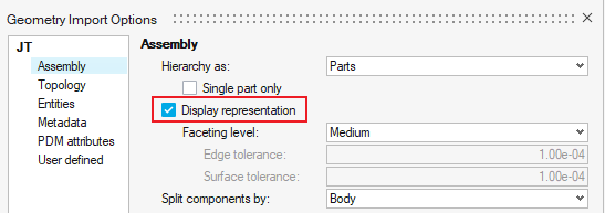
Display Representation
A new lightweight visualization mode of geometry is supported for CAD
formats. Supported geometry file formats are: Acis, Catia, CatiaV6,
Creo, Inspire, Inventor, JT, Rhino, NX native, NX third party,
Parasolid, SLDPRT/SLDASM, STEP, and VDAFS. Figure 30. Import Geometry Figure 31. Import BOM
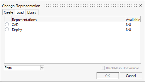
This mode, called Display Representation, is available through import
geometry or load representations in the Part Browser. It provides
improved import and graphical performance, and offers a convenient way
to perform initial inspections of the model. Once the Display
Representations have been reviewed, you can optionally load in the full
geometry via Representation > Load or submit parts straight to BatchMesher via Representations > Create.
OpenPDM Connection
New PDM Connector, OpenPDM, is now supported.
OpenPDM facilitates the better flow of information between different PLM
systems. By using OpenPDM connector, HyperMesh can work with any PLM
system that integrates with OpenPDM seamlessly.
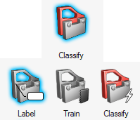
Classify Tool
The Classify tool, a machine learning tool, has been added in the new
AI/ML section of the Assembly ribbon. This tool exploits the benefits of
machine learning (ML) to auto-assign labels to parts based on their
shape. Each label starts out being manually created and assigned by the
user to help the ML model learn what parts look like. Once you have
assigned Labels using your own data, you train a model which can then be
used to Classify parts on new models. The goal is to automate the
process of part identification and classification to reduce manual
effort of organizing a large model. Figure 32.
New Curve Editor
The Curve Editor has been upgraded and given a new look to support some
additional features. Tables in the Curve Editor now supports import of
tabular data from csv files, direct export to
csv, manipulation of data inside a table, such
as inserting or deleting rows anywhere in the table, and copy and paste
from within or from outside, without any limitations. Curve operations
are also supported, such as duplicate a curve, hide, show or isolate a
curve with the right-click context menu, Fit all function in the
right-click context menu or keyboard shortcut F, and search and filter
curve names from within the Curve Editor.
Renumber All
The Renumber All method has been added to the Renumber tool. With this
option, all entities of all types in the model are renumbered at
once.
Enhancements
Save Representation Workflow Updates
The save representation workflow has been enhanced by allowing the save
of only modified parts. Modifications to parts are tracked so we can
automatically only save the parts that need saving. Figure 33.
Sections and Sensor Entities Saved into Part Representations
Sections and Sensor entities are saved into part representations, which
better supports Ansys workflows.
Saving Representations Performance Improvements
Performance enhancements have been made to improve the time taken to
save representations.
Default Settings Updated for the RBE3 Tool
The default settings of the RBE3 tool have been updated so that the
weighting coefficients for independent DOF are a constant 1.0. The
distance-weighted coefficient method is still available to use in the
tool, but it is no longer the default.
Resolved Issues
Slowdowns with selection and renumbering of large models in the Renumber tool have
been resolved.
Model Verification
Enhancements
Shape AI Digital Signature Calculation
Shape AI Digital Signature Calculation added for Part Match function and
stores the calculated value in Part attributes.
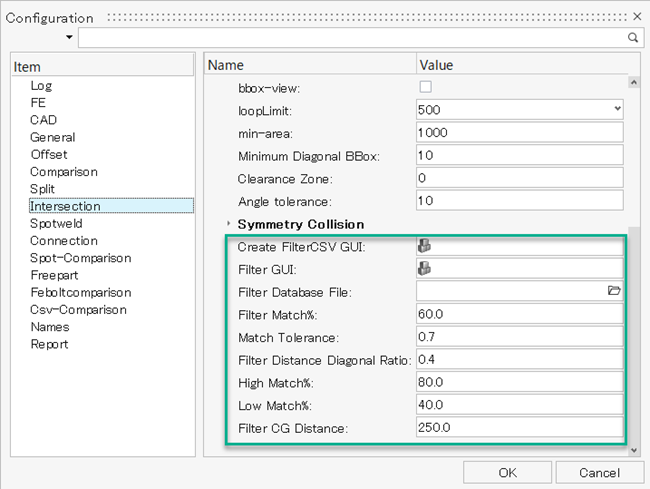
Intersection Database File
Intersection Database file can be created from previous ran Intersection
results, file will contain Digital Signature, BBOX attributes, XYZ
intersection location information for all the Parts.
Intersection Check Function
Intersection Check function reads Part's Database (Digital Signature,
BBOX attributes, XYZ intersection locations), compares it with Variant
model's attributes and segregates Intersection Reports to Filtered and
Non_Filtered groups. If the Part's BBOX, Digital Signature, Intersection
Locations are compared with Variant Part's attributes, if the comparison
results are within limit set in configuration, then its reports is
organized to Filtered Group. Figure 34.
Intersection Automatic Renumbering of Parts
Intersection will automatically renumber parts if duplicate PID exist,
it takes max ID + increment.
Log Information
All log information are unified to have PIDs for Comparison.
Resolved Issues
Configuration File: Exporting Configuration file pointing to the
:C drive instead of the working directory has been
fixed.
Intersection Report: No entities found in Sphere creation error has been
fixed.
Quick comparison no longer fails for certain JT assembly model.
Spot Extraction no longer fails for certain JT model.
Morphing
Enhancements
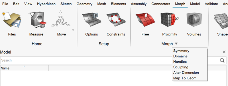
Panel Migration into Controllers
Figure 35.
The same tool functionality available in the Panels can now be
found in the Morph drop-down.
Domains and Handles can be Morphed by using the Free Morph context.
Move/Mirror/Scale can now manage Shapes.
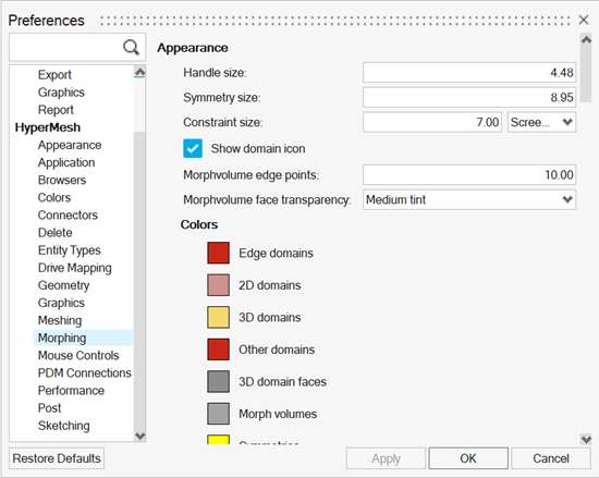
Morph Options are now available in the Preferences area: Figure 36.
Morph Volumes
The Main-Secondary Tangency arrow direction has now been updated to
point from Main to Secondary. Historically, it would point from
Secondary to Main.
Resolved Issues
Corrected issue with "on elems" in morph constraint, "maintain" and "along
vector" options, projecting erratically.
Plots
New Features
Chart Entity
It is now possible to create and edit charts for visualization purposes.
The Chart entity type has been added.
In this release, the Chart entity supports Line charts. More types will
be supported in the future.
The Chart entity accepts data from one of the following sources: direct
input XY values, table entity created in HyperMesh, such as those using
the Matrix Browser, or results loaded in Post.
When selecting results as source, charts for selected entities and
selected data types are supported for the current subcase. More options
will be added in upcoming releases.
Known Issues
For Chart entities, the direct input table does not record a tcl command.
This will be added in upcoming releases. For automation, the Matrix table
option can be used.
Post
New Features
Marker Plot
Results plots can now be requested in the form of text on the screen,
also known as Marker plots. Just like contour, vector, and tensor plots,
Marker plots store a result definition and list of entities.
A mini legend that comes with Marker plots indicates the
currently plotted result in the marker.
It can be overlaid with any other plot type.
Basic manipulation of text such as text color, show hide, and
multi line is supported.
Enhancements
Result Query Tools
Exposed via GUI through Preference
Post (and in batch xml mode):
Output format can now also be set in Scientific mode (previously
was only fixed format).
Output file can be written removing the header part.
Exposed only through XML syntax:
Possible to overwrite global settings in each query
definition.
Possible to set label ALL on load case selection.
Possible to set Projection Rules with Global or User
System.
Derived Loadcase Workflow
The derived loadcase workflow has been enhanced. Some of the notable
updates are:
Support for Envelope-Extreme loadcase.
Layer/System/Averaging method and Corner Data can be specified
when defining Envelope metric.
Delete or rename Derived loadcases from Results Browser.
Review Derived loadcase definition in Entity Editor.
Category Based Legends for Contour Plot
A category based legend will now be displayed for the following types of
contour plots:
Airbags: New attributes added in *DEFINE_CPM_VENT.
Constrained: New attributes and optional card added in
*CONSTRAINED_INTERPOLATION_SPOTWELD.
Contacts: Optional Card added in *CONTACT. Multiple updates and
corrections in *CONTACT_2D_AUTOMATIC_SURFACE_TO_SURFACE,
*CONTACT_2D_AUTOMATIC_TIED.
Elements: New attribute NEND added in *ELEMENT_SPH.
Materials: New attributes added in *MAT_ADD_DAMAGE_GISSMO,
*MAT_ADD_GENERALIZED_DAMAGE, *MAT_196, *MAT_224, *MAT_240, *MAT_252,
*MAT_SAMP-1, *MAT_LAMINATED_COMPOSITE_FABRIC.
Sensors: New attribute TDELAY in *SENSOR_SWITCH. Number of switch
sensors increased to 14 in *SENSOR_SWITCH_CALC-LOGIC.
LS-DYNA I10 Format
Support of long=s in *KEYWORD along with i10=y. Long=s can be added via
the solver deck export options when i10 format is activated.
Performances
Relevant performance improvements made in the Model Checker.
Resolved Issues
A correction has been made in the Position/Transformation tool when
Positions are applied or un-applied. Only selected Position is now affected
and performances are improved.
Card4 in *MAT_SEATBELT_2D is now treated as optional.
Export issue of *CONTROL_MPP_DECOMPOSITION_TRANSFORMATION has been
fixed.
Multiple corrections have been made in reading and editing
*MAT_3-PARAMETER_BARLAT_(OPTIONS). Anisotropy axis definition attributes are
read and maintained on export independently from the AOPT value.
A correction in reading *MAT_ORTHOTROPIC_ELASTIC has been made. Anisotropy
axis definition attributes are read and maintained on export independently
from the AOPT value.
A correction in reading *MAT_LAMINATED_COMPOSITE_FABRIC has been made. AOPT
value wasn't read properly.
A correction in reading *SENSOR_SWITCH_CALC-LOGIC has been made.
*ELEMENT_SPH attributes are now fully exposed in the Entity Editor.
Show/Hide/Isolate/Review operations are now working on Position entity when
defined on *INCLUDE_TRANSFORM.
Nastran Interface
Enhancements
Moved Super Elements Creation Process
Super elements creation has been moved from the panel to the controller
workflow in the Elements ribbon.
Drive Mapping Support
Drive Mapping is now supported on Export of solver decks, enabling you
to work with solver decks across operating systems.
Resolved Issues
Load (superposition) not allowing selection of other Load entities has been
resolved.
Export performance delay while exporting model with spring elements has been
resolved.
OptiStruct Interface
Enhancements
Moved OptiStruct Thermal Cards
OptiStruct thermal cards have been moved to the appropriate HyperMesh
entities for ease of thermal analysis setup.
Card
From HyperMesh Entity Type
To HyperMesh Entity Type
CHBDYE
Groups
Set Segment
CONV
Groups
Load
PCONV
Groups
Property
Set Entity
Set entity has been enhanced to support BOOLEAN operator subtype in
SET_GRID and SET_ELEM set types.
Moved OSSMOOTH
OSSMOOTH has been moved from the panel to the controller workflow in the
Optimize ribbon.
Moved Gauge and Shape Optimization Setup
Gauge and Shape optimization setup has been moved from the panel to the
controller workflow in the Optimization ribbon.
Drive Mapping Support
Drive Mapping is now supported on Export of solver decks, enabling you
to work with solver decks across operating systems.
Resolved Issues
Issue where you were unable to select a subcase for STATSUB(BUCK) through
the Entity Editor has been resolved.
Issue where PACPML's node id was missing in the exported OptiStruct input
file has been resolved.
Issue with the wrong vector fields export for GRIDCON in DSHAPE card with
vertex option has been resolved.
Issue with deletion of pretension surf from browser cause application in
pretension manager has been resolved.
Issue with incorrect export of SN line in MATFAT definition has been
resolved.
Issue with user comments not being written for PLY card on export has been
resolved.
Issue with component information being lost while importing input file with
plane strain element definition has been resolved.
PAM-CRASH Interface
New Features
Modular Material MMAT 2020
New MMAT 2020 is now supported along with Legacy MMAT.
Modular Part - MPART implementation.
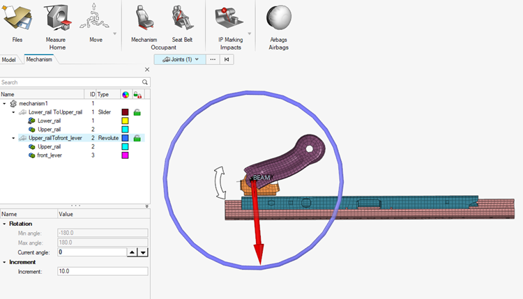
Mechanism Tool
The Mechanism tool is now exposed in PAM-CRASH interface. Figure 38.
Enhancements
Group Entity Selection Improvements
Selectors of entities in the Group Entity Editor (Contact, Mass_GES
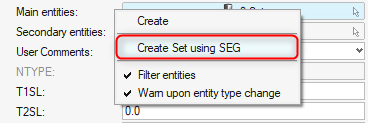
& NSMAS) are now only with 'Set' selector.
From the context menu of the Set selector, Set can be created using SEG
Elements by selecting Faces, Facets, Edges in the microdialog and by
creating those elements simultaneously: Figure 39.
Resolved Issues
Mass calculation results for the NSMAS and NSMAS2 keywords have been
corrected when MLEN, MARE, and MVOL parameters are defined.
Permas Interface
Enhancements
New Set Segment Entity
The $SURFACE and $SURFACE GEO cards have been migrated from contact
surface to setsegment.
Radioss Interface
Enhancements
New Supported Keywords
New supported keywords: /FAIL/GENE1, /FAIL/RTCL, /FAIL/SAHRAEI,
/H3D/SPH/(OPTION), /MAT/101, /MAT/LAW121, /SURF/ELLIPS.
Updated Keywords
There are new attributes in /LOAD/PBLAST.
There are new attributes in /INTER/TYPE21.
There are new attributes in /INTER/TYPE24.
There are new attributes in /INTER/ TYPE25.
Performances
Relevant performance improvements made in the Model Checker.