Create weld points at a predefined pitch distance so that the model build process can
continue without the need to wait for the published weld data from CAD. Autopitch is useful
when working with elements, not geometry.
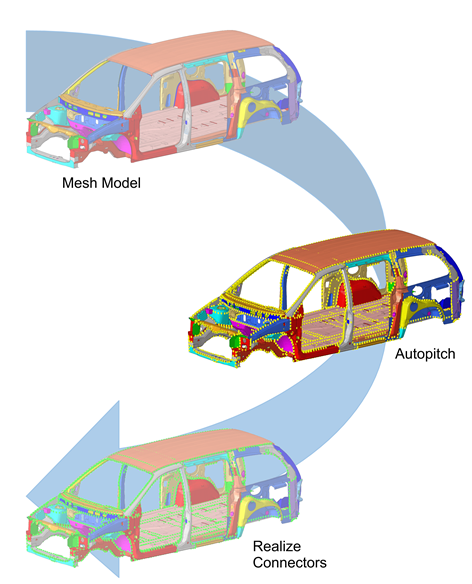
Figure 1. . Starting with a CAD model, the Autopitch tool creates unrealized connectors
(yellow) which are then realized via the Spot panel.
From the menu bar, click Connectors > Create > Autopitch.
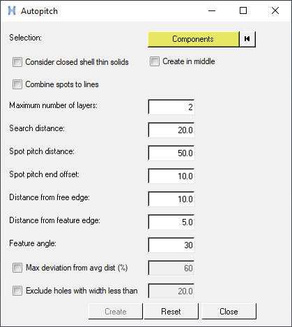
The Autopitch dialog opens. Figure 2.
Using the Components selector, select the components to automatically add
connectors to.
All selected components receive connectors with the same qualities to help you
perform a blanket application of connectors – using the same pitch – to all
components that need them as a single operation. Be wary of simply selecting the
whole model, however, as this could result in undesirable actions, such as
adding welds to a car's tires.
To use shell meshes that enclose a volume (some small gaps are allowed) as
input, enable the Consider closed shell thin solids
checkbox.
For example, the outer skin of a solid part can be shell meshed and used as
input to create connectors. Standard mid-plane meshes are also still considered
when this option is used.
To create connectors in the middle of the found flanges, enable the
Create in middle checkbox.
By default, connectors are created on either one of the flanges. This applies
to both mid-plane and closed shell thin solid inputs, when appropriate.
To combine a series of spot connectors into a spot-line connector, enable the
Combine spots to lines checkbox.
Define settings.
In the Maximum number of layers field, enter the maximum number of
layers for the connector to add.
In the Search distance field, enter the distance to consider between
components.
In the Spot pitch distance field, enter the distance between each
connector.
In the Spot pitch end offset field, enter the distance from the end of
an edge/flange to the connector.
In the Distance from free edge field, enter the distance from the free
edge to the connector.
In the Distance from feature edge field, enter the distance from
feature edge to connector.
In the Feature angle field, enter the angle used to segregate the model
into faces that are planar within its specified value.
In the Max deviation from avg dist (%) field, enter the average
distance that can be calculated based on the estimation that the
distance between two flanges does not change too much in the areas where
connectors should be placed.
If the distance at the position where a connector is planned exceeds
the given deviating value, no connector will be created at that
position.
This segregation is used to identify where autopitch connectors are
placed. For example, faces found to have significant topological
complexity are not used to create autopitch connectors.
Note: By reducing its value, the complexity of some of these faces is
generally reduced. Of course, flat regions are unaffected by the
parameter.
To filter holes from the flange search if under a defined width, enable
the Exclude holes with width less than checkbox,
then type the appropriate value into the field.
Click create.
The created output is connectors with the appropriate spacing and other associated
parameters. The connectors are in the unrealized state.
The output is organized in the current component collector. If there is no current
component collector, then a new collector called ^autopitch is created.