About Representations
The CAD representation is typically the original source of information of what a physical part will look like.
It forms the basis of the Display and Common representations, the latter being in turn the basis of all subsequent discipline-specific mesh representations (Figure 1). Display representation offers the ability to import a CAD file in a visualization mode only. A part can contain multiple representations.
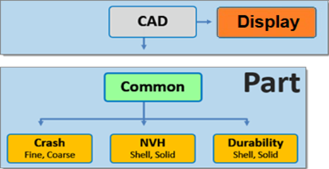
Figure 1. Hierarchical Relationship of Representations
The Display representation is only a geometry preview of the model, it does not contain any actual geometric entities and/or FE mesh.
A folder-based Representation repository stores all CAE data that is required during the model build and assembly process. CAE data stored in the Representation repository includes the geometric and FE representation of the parts that comprise the subsystem specific model hierarchy.
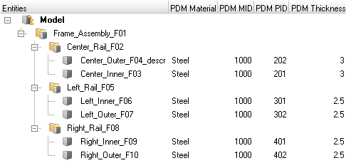
You can import a BOM via a neutral file format such as PLMXML or manually create a part structure using the Part Browser context menu.
Common Representation
The Common representation is derived from the CAD representation and forms the basis of all subsequent discipline specific mesh representations.
For sheet metal parts, the Common representation consists of midsurfaced geometry or FE. The CAD is sent to the BatchMesher for midsurface extraction; upon completion it is saved into the repository and you can elect to immediately import the representation into the session.
HyperMesh entities are generated from the PDM metadata, if available, in the post-run procedure of the BatchMesh operation. The PDM PID is assigned to the component and property, the PDM MID and PDM material is assigned to the material and the PDM Thickness is assigned to the Thickness attribute of the property. If the PDM Thickness is blank, the CAD Thickness calculated during the midsurface operation is automatically assigned to the Thickness attribute of the property.
For parts such as castings and tailor-welded blanks, you can save CAD representations as Common models.
Alternatively, you can send solid parts to the BatchMesher. If thin-solid detection is enabled in the Common representation parameter file, then solids will be detected and saved as the Common representation without processing. By default, the midsurface algorithm skin is used. CAD representation does not need to be loaded into the session in order to generate the Common representation since it is sent directly to the BatchMesher for processing.
When you select a discipline specific mesh representation from the Change Representation dialog, Create tab, the Common representation residing in the repository is automatically sent to the BatchMesher for processing. If the Common representation does not exist it will be automatically generated.
Display Representation
The main purpose of this tool is to provide a lightweight version of imported geometry that allows fast loading of large assemblies, leading to significant time savings. This is a convenient way to perform initial inspections of the model. You can select the Display representation option when importing Geometry files (Figure 2) and after importing a BOM file (Figure 3).
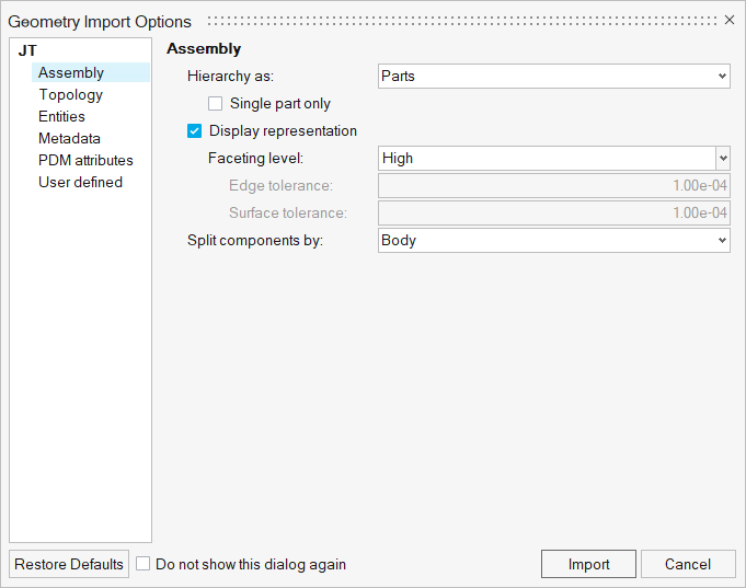
Figure 2. Importing Geometry
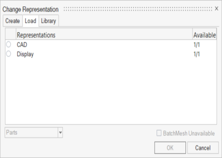
Figure 3. Display selection
Supported geometry file formats are: Acis, Catia, CatiaV6, Creo, Inspire, Inventor, JT, Rhino, NX native, NX third party, Parasolid, SLDPRT/SLDASM, STEP, VDAFS.
Respective import options can be accessed from the Part Browser using the context menu .
- Choose Low to set the faceting level to the lowest level.
- Choose Medium to set faceting level to its normal (default option).
- Choose High to set the faceting level to its maximum.
- Choose Custom to set the edge and surface tolerance manually (default: 1e-04).
Discipline Specific Mesh Representations