Exercise 2: Define Boundary Conditions and Loads for the Head and A-Pillar Impact Analysis
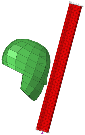
In this exercise, you will define LS-DYNA boundary conditions, loads, and contacts in Engineering Solutions. Also, you will set up the boundary conditions and load data for a LS-DYNA analysis of a hybrid III dummy head impacting an A-pillar.
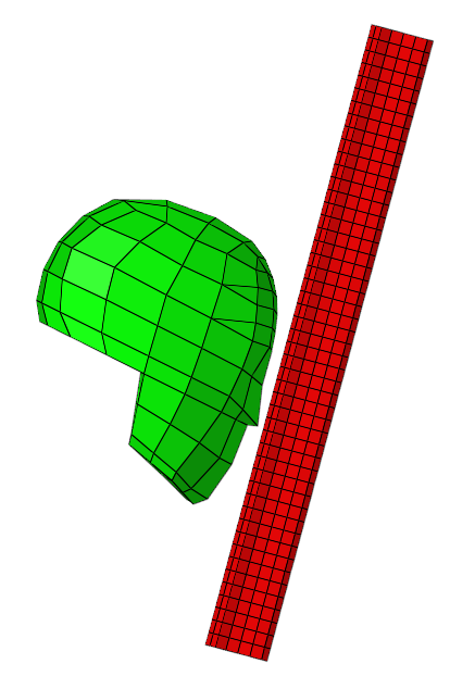
Figure 1.
Load the LS-DYNA User Profile
In this step, you will load the LS-DYNA user profile in Engineering Solutions.
- Start Engineering Solutions Desktop.
- In the User Profile dialog, set the user profile to LsDyna.
Retrieve the Engineering Solutions File
In this step, you will open the Engineering Solutions model file.
Create a Node Set
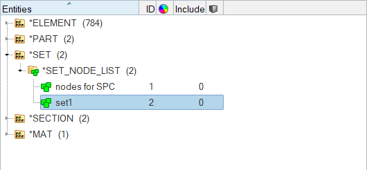
In this step, you will create a node set, *SET_NODE_LIST, which will contain all of the nodes in the head component of the model.
Define the Velocity
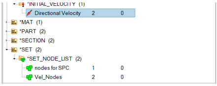
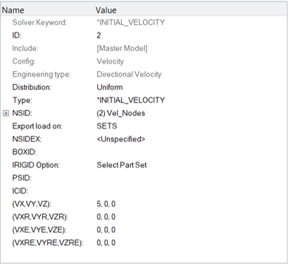
In this step, you will define the velocity for the model.
Create a Load Collector
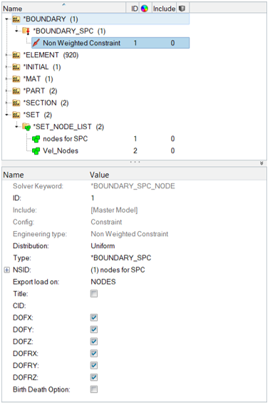
In this step, you will create a load collector for the constraints to be created.
Create Constraints on the Pillar's End Nodes
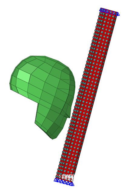
In this step, you will create constraints on the ends of the pillar component of the model.
Define a *SET_SEGMENT for the Secondary Entities
In this step, you will create a new contactsurf on the pillar element of the model.
Define a *SET_SEGMENT for the Main Entities
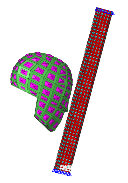
In this step, you will create a contactsurf on the head component of the model.
Create a Engineering Solutions Group
In this step, you will create a Engineering Solutions group with the SurfaceToSurface card image.
Add the Secondary and Main Contactsurfs to the Engineering Solutions Group
In this step, you will add the secondary and main contactsurfs to the Engineering Solutions group.
Edit the Group card image
In this step, you will define the automatic option for the group in Engineering Solutions.
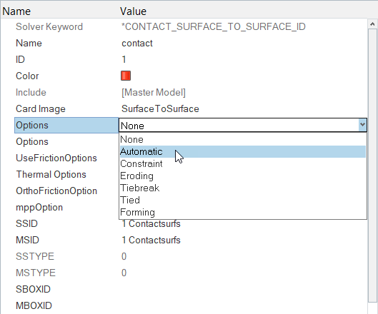
Figure 15.
Review the Group Main and Secondary Surfaces
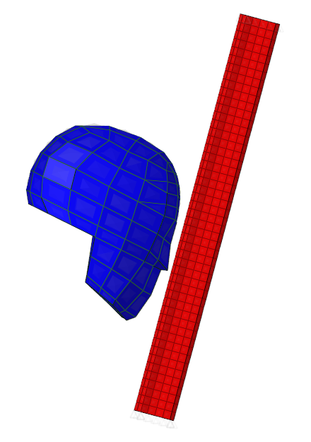
In this step, you will review the main and secondary surfaces for the group.
Save Your Work
In this step, you will save your work in Engineering Solutions.
