Element and Ply Visualization
The exact visualization of ply layers in a composite material requires the use of both the Composite Visualization and Element (complexity) Visualization options.
These options work in tandem to determine exactly how composite layers will display in Engineering Solutions.
 (1D/2D
Element Representation)
 (Composite
Visualization)
- 2D Traditional Element Representation (
 )
) - Engineering Solutions represents composite layers, when visible,
as 2D shells:
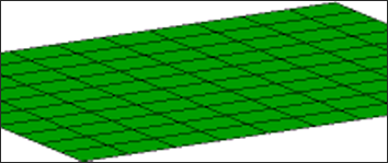
Figure 1. Layers Off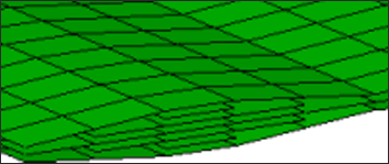
Figure 2. Composite Layers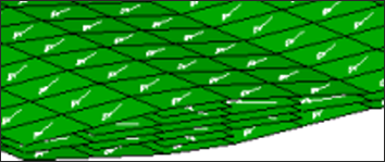
Figure 3. Layers with Fiber Direction - 2D Detailed Element Representation (
 )
) -
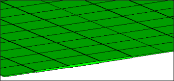
Figure 4. Layers Off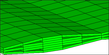
Figure 5. Composite Layers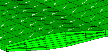
Figure 6. Layers with Fiber Direction - 2D Traditional and Detailed Element
Representation (
 )
) -
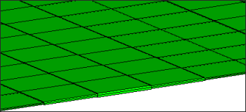
Figure 7. Layers Off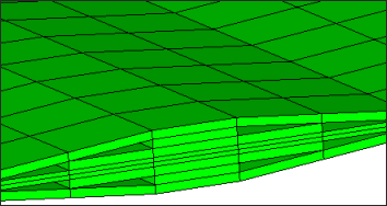
Figure 8. Composite Layers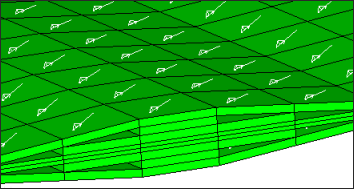
Figure 9. Layers with Fiber Direction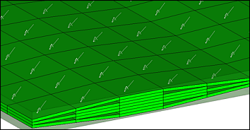
Figure 10. Layers with Fiber Direction for Continuum Shells. Original element geometry is shown in transparent mode, so that differences in elemental versus property thickness can be easily seen.