Mechanism Browser
Create and articulate a kinematic mechanism based on FE mesh using the Mechanism Browser.
From the menu bar, click .
You can undo and redo actions made in the Mechanism Browser using the Undo and Redo commands on the Restore toolbar.
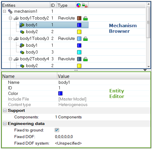
Figure 1.
| Column | Description |
|---|---|
| Entity | Lists the mechanism, joints, bodies, and constraints in your model. |
| ID | Displays the mechanism, joints, bodies, and constraints IDs. |
| Type | Displays the joint or constraints type. |
| Color | Displays the joint and body entity colors. Body color is different from the component color set-up in the Model Browser. The body color is activated when a body is in Review mode. |
| Lock level | Displays the lock level of a joint (green = free joint, yellow = locked joint). |
Entity Editor
The Entity Editor is used to assign, modify and quickly view the attributes defined inside Mechanism Browser entities.
For example, once you create a new body or select a body in the browser, the Entity Editor opens and displays the bodies corresponding attributes, which you can view and modify.
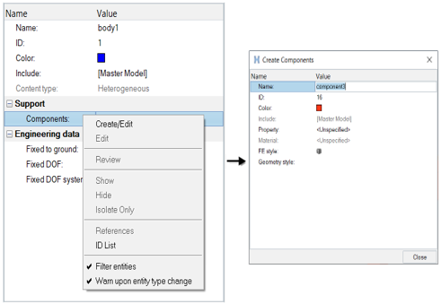
Figure 2.
Context Menu
Supported Entities
- Bodies (
 ) define
a kinematic assembly made of FE parts or nodes, which can be selected in the
Entity Editor. To create a body, right-click on
the Mechanism and select from the context menu.
 - Joints (
 ) define
the kinematic relationship between two bodies (for the following joint
types: Ball, Cylinder, Revolute, Slider) or three bodies (for the
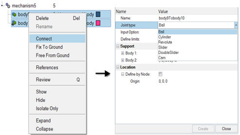
DoubleSlider joint). To create a joint, select two bodies to connect in the
browser, then right-click and select Connect from the
context menu. For the DoubleSlider joint, the
third body has to be defined in the Entity Editor.
 - Constraints (
 ) define
kinematical constraints on a body at a specified node or point
location.
Supported Keywords Exported in Solver Deck
The mechanism information is embedded in the input deck using keywords following the /END (for Radioss), *END (for LS-DYNA), ENDDADTA (for OptiStruct/Nastran) and *END STEP (for Abaqus).
- $ASSEMBLY defines a body with the following
attributes:
- Assembly ID
- Assembly name
- Number of part sets and related set IDs
- Number of parts and related part IDs
- Number of node sets and related set IDs
- Locked degrees of freedom
- Optional local coordinate system
- $CONNECTION defines a joint between assemblies with the
following attributes:
- Connection name
- Assembly ID #1
- Assembly ID #2
- Connection position (defined by Node IDs or connection position coordinates)
- Joint limits in + and - directions
- Current joint distance/angle value
- Lock level
- Assembly ID #3 (for the Double Slider only)
- Scale factors for relative displacement between Assembly #3 and Assembly #1 and #2
- $POSITION defines, for a stored position, the position
information for the mechanism’s assemblies with the following attributes:
- Position name
- Assemblies position matrixesNote: The Reference and Initial positions should never be deleted inside the mechanism.
- The following connection keywords can be defined depending on the type of
joint created:
- $CONNECTION_PIN defines a ball joint
- $CONNECTION_HINGE defines a revolute joint
- $CONNECTION_CAM defines a cam joint
- $CONNECTION_LINE defines a cylindrical joint, or a double slider joint if assembly ID #3 is defined or a slider joint has the #HM_SLIDER_JOINT comment defined before the name of the connection
Create Mechanisms
Create a mechanism for Abaqus, OptiStruct, and Nastran profiles.
Mechanisms are created using a manual approach only.
Modify the Position of Mechanisms
Modify the Position of Joints
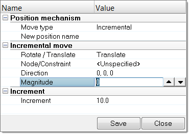
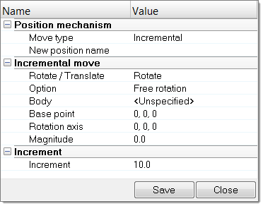
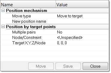
- In the Mechanism Browser, right-click on a joint and select Move from the context menu.
-
Modify the position of the joint.
- In the graphics area, click-and-drag the manipulator.
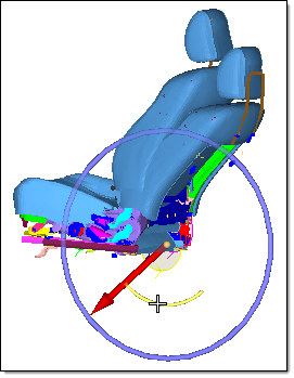
Figure 8. - In the Entity Editor, modify the Current angle
of the joint.
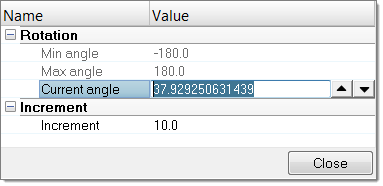
Figure 9.
- In the graphics area, click-and-drag the manipulator.
- Change the Increment value to control the increments of the operation.

