HM-1040: Control the Display

When performing finite element modeling and analysis setup, it is important to be able to view the model from different vantage points and control the visibility of entities. You may need to rotate the model to understand the shape, zoom in to view details more closely, or hide specific parts of the model so other parts can be seen. Sometimes a shaded view is best, while other times, a wireframe view allows you work on details inside the model. HyperMesh has many functions to help you control the view, visibility, and display of entities.

In this tutorial you will learn how to:
  • Control the points of view using the mouse and toolbar.
  • Control the visibility of entities using the Display panel, Mask panel, and tools on the Utility menu.
  • Control how entities look by using the toolbar and the Model Browser.
  • Rename components.
  • Identify and delete empty components.
  • Delete all of the geometry lines.
This exercise uses the following model file, which can be found in the hm.zip file:
  • bumper.hm

Copy the file from this directory to your working directory.

Open the Model File

In this step you will open the model file, bumper.hm.

  1. Start HyperMesh Desktop.
  2. From the menu bar, click File > Open > Model.
  3. In the Open Model dialog, navigate to your working directory and open the bumper.hm model file.
    A model appears in the graphics area.

Manipulate the Model

In this step you will learn how to use Ctrl + mouse buttons to rotate the model, and change the center of rotation, zoom, fit, and pan.

  1. Move the mouse pointer into the graphics area.
  2. Press Ctrl + left mouse button (LMB) and move the mouse around.
    The model rotates with the movement of the mouse, and a small white square appears in the middle of the graphics area, indicating the center of rotation.
  3. Release the LMB and press it again to rotate the model in a different direction.
  4. Press Ctrl and quick-click the LMB anywhere on the model.
    The center of rotation square appears where you clicked and HyperMesh searches for one of the conditions listed below, in the listed order, and relocates the center of rotation at or near the first condition identified:
    • A nearby node or surface vertex
    • A nearby surface edge to project onto
    • A nearby geometry surface or shaded element

    If none of the conditions are met, the center of rotation is relocated to the center of the screen.

  5. To rotate the model and view the change in rotation behavior, press Ctrl + LMB.
  6. Press Ctrl and quick-click the LMB anywhere in the graphics area, except for on the model.
    HyperMesh relocates the center of rotation square to the center of the screen.
  7. To rotate the model and observe the change in rotation behavior, press Ctrl + LMB.
  8. Press Ctrl + Middle Mouse Button (MMB) and move the mouse around.
    HyperMesh draws a white line along the path of the mouse movement.
  9. Release the mouse button.
    HyperMesh zooms in on the portion of the model where the line was drawn.
    Note: You can also draw a line to zoom in on a portion of the model.
  10. Press Ctrl + quick-click the MMB.
    HyperMesh fits the model to the graphics area.
  11. Press Ctrl and spin the mouse wheel.
    HyperMesh zooms in or out on the model depending on which direction you spin the mouse wheel.
  12. Move the mouse pointer to a different location in the graphics area and repeat Step 11.
    HyperMesh zooms in or out on the model from where the mouse handle is located.
  13. To fit the model to the graphics area, press Ctrl + quick-click the MMB.
  14. Press Ctrl + Right Mouse Button (RMB) and move the mouse around.
    HyperMesh pans (translates) the model according to the mouse movement.

Manipulate the Model View

In this step you will manipulate the view of the model using the rotate functions on the toolbar.

  1. On the view controls toolbar, left-click (Dynamic Rotate).
  2. Move the mouse pointer into the graphics area.
    The center of rotation square appears.
  3. Press and hold the LMB, and then move the mouse around.
    The model rotates with the movement of the mouse, similar to the way the model rotates when you press Ctrl + LMB and move the mouse.
  4. Click the MMB on the model.
    The center of rotation square appears near where you clicked.
  5. To exit the rotation mode, move the mouse pointer out of the graphics area or right-click.
  6. On the View Controls toolbar, right-click (Dynamic Rotate) and move the mouse pointer into the graphics area.
    The center of rotation square appears.
  7. To change the center of rotation, click the MMB on the model.
  8. Click the LMB near the center of rotation square.
    The model rotates continuously in the direction of your mouse pointer relative to the center of rotation.
  9. With the LMB still pressed, move the mouse around slowly.
    The direction and speed of the rotating model changes.
    Note: The farther the mouse pointer is from the center of rotation, the quicker the model rotates.
  10. To rotate the model in a different direction, release the LMB and then click it again.
  11. Click the MMB anywhere in the graphics area, except on the model.
    The center of rotation square relocates to the screen center.
  12. To exit the rotation mode, move the mouse pointer out of the graphics area or left-click.

Manipulate the Model View using Zoom

In this step you will manipulate the view of the model using the zoom in and out functions on the toolbar.

  1. On the View Controls toolbar, left-click (Circle/Dynamic Zoom).
    The Status bar displays the message, "Circle the data to be zoomed in on."
  2. Move the mouse pointer into the graphics area.
  3. Press the LMB and move the mouse around the graphics area.
    HyperMesh draws a white line along the path of the mouse movement.
  4. Release the LMB.
    HyperMesh zooms in on the portion of the model where the line was drawn.
    Note: You can also draw a linear line to zoom in on a portion of the model. This function is similar to pressing Ctrl + MMB to zoom into a portion of the model.
  5. On the Standard Views toolbar, click (Fit).
    HyperMesh fits the model to the graphics area.
  6. On the View Controls toolbar, left-click (Zoom In/Out).
    HyperMesh zooms in on the model by the factor specified in the Options panel.
  7. On the View Controls toolbar, right-click (Zoom In/Out).
    HyperMesh zooms out on the model by the same factor.
  8. To open the Options panel, click Preferences > Meshing Options or Geometry Options from the menu bar.
  9. Go to the geometry or mesh subpanel.
  10. In the zoom factor = field, type 4.
  11. To exit the panel, click return.
  12. On the View Controls toolbar, left-click (Zoom In/Out).
    HyperMesh zooms in on the model by the larger, specified factor.
  13. On the View Controls toolbar, right-click (Zoom In/Out).
    The Status bar displays the message, "Drag up/down to zoom in/out."
  14. Move the mouse pointer into the graphics area, press the LMB, and then move the mouse pointer up and down.
    HyperMesh zooms in and out on the model according to how far you move the mouse up or down.
  15. To exit the dynamic zoom mode, move the mouse pointer out of the graphics area or left-click.

Manipulate the Model View Using Arrows

In this step you will manipulate the model view using the arrows and the View panel on the toolbar.

  1. On the View Controls toolbar, right-click or left-click any of the Rotate icons ( , , ).
    The model rotates in the direction of the arrow by the rotation angle specified in the Options panel.
  2. On the Standard Views toolbar, click (XY Top Plane View).
  3. To open the Options panel, click Preferences > Meshing Options or Geometry Options from the menu bar.
  4. In the rotate angle = field, type 90.
  5. To return to the main menu, click return.
  6. On the View Controls toolbar, click any of the Rotate icons ( , , ).
    The model rotates by the new specified rotation angle, 90.
  7. Change the view of the model to any view.
  8. To rotate the model, press Ctrl + LMB, or click any of the Rotate icons on the View Controls toolbar.
  9. To zoom in or out on the model, press Ctrl + MMB, or click any of the Zoom icons on the View Controls toolbar.
  10. From the Model Browser, right-click anywhere and select Create > View from the context menu.
  11. To see the new view name, expand the View folder.
  12. Right-click on the view and select Rename from the context menu.
  13. In the editable field, type my_view for the new name.
  14. To display a different view of the model, click (XY Top Plane View).
  15. To display the view, click my_view in the Model Browser.

Control the Display of Components

In this step you will control the display of components using the toolbar.

  1. On the Visualization toolbar, click (Shaded Elements and Mesh Lines).
    HyperMesh shades the model's shell elements.
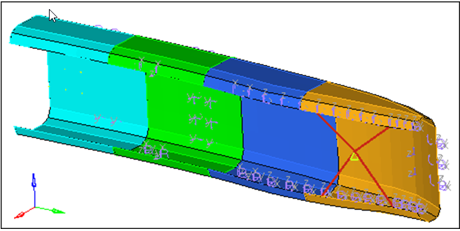
  2. Left-click the down arrow next to (Shaded Elements and Mesh Lines), and select (Shaded Elements and Feature Lines).
    HyperMesh shades the model's elements and displays the feature lines. Mesh lines are no longer displayed.


    Figure 1.
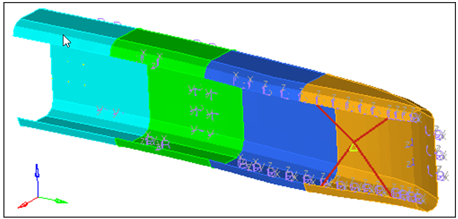
  3. Left-click the down arrow next to (Shaded Elements and Feature Lines), and select (Shaded Elements).
    HyperMesh hides the model's feature lines.


    Figure 2.
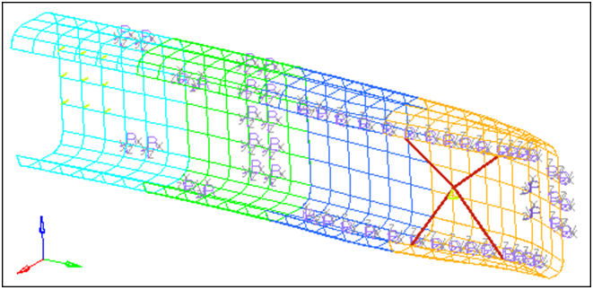
  4. To return to the wireframe shading mode, click (Wireframe Elements Skin Only) on the Visualization toolbar.


    Figure 3.

Control the Display of Components Using the Model Browser

In this step you will control the display of components using the Model Browser.

  1. On the Visualization toolbar, click .
    HyperMesh shades all of the model's elements with no mesh lines.
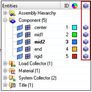
  2. In the Model Browser, right-click on an empty space on the column heading bar and select Show FE Style from the context menu.
    A new column appears in the Model Browser.


    Figure 4.
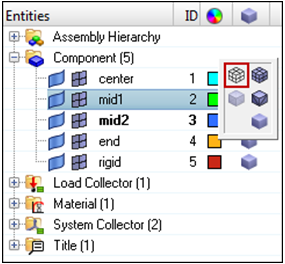
  3. For the mid1 component, left-click in the FE Style column.


    Figure 5.
  4. From the pop-up menu of display modes, select (Wireframe Elements Skin Only).
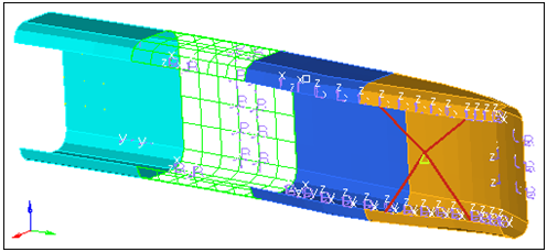
    HyperMesh changes only the mid1 components display mode to wireframe.


    Figure 6.
  5. Experiment with other display modes.
    Wireframe Elements – edges are displayed with lines.
    Wireframe Elements Skin Only – edges are displayed with lines for shell elements only.
    Shaded Elements – element is displayed as a filled polygon.
    Shaded Elements with Mesh Lines – element is displayed as a filled polygon with the feature edges drawn in mesh line color.
    Hidden Line with Feature Lines – element is displayed as a filled polygon with the featur4e edges in mesh line color.
    Transparent – element is displayed as a filled transparent polygon.

Control the Visibility of Entity Categories

In this step you will control the visibility of entity categories using the Model Browser.

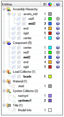
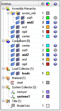
  1. In the Model Browser, right-click and select Expand All from the context menu.
    All of the folders in the browser expand.
  2. At the top of the browser, click (Display none).
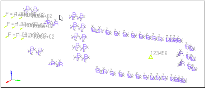
    HyperMesh turns off the display of all the entities in the model.


    Figure 7.
  3. Click (Display all).
    HyperMesh displays all of the entities in the model.


    Figure 8.
  4. Left-click Components (5) to select all of the components in the model.
  5. Click (Display none).
    HyperMesh turns off the display of all the component collectors.
    Note: Display all, Display none, and Display reverse act globally (on all entities) if you have not selected any of the entities in the Model Browser. If a folder is selected (highlighted), HyperMesh will perform the action only on the entities within that folder. If an individual entity is selected, HyperMesh will perform the action only on that entity.


    Figure 9.
  6. Left-click in the white space of the browser.
    HyperMesh deselects all of the entities in the browser.
  7. Click (Display reverse).
    HyperMesh reverses the display and only shows the components, instead of everything but the components.
  8. Click (Components View).
    HyperMesh displays only the component collectors in the browser.
  9. At the top of the browser, click the down arrow next to (Elements and Geometry Filter), and select (Elements).
    Note: Display all, Display none, and Display reverse will no longer affect the display of the geometry in the components.
  10. Click (Display none).
    HyperMesh only displays the components geometry.
  11. Set the elements and geometry filter to (Elements and Geometry).
  12. Click (Display reverse).
    HyperMesh only displays the component's elements.

Control the Visibility of Components Using the Model Browser

In this step you will control the visibility of individual components using the Model Browser.

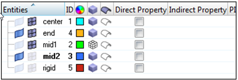
A component collector has two ‘compartments’: one for elements and the other for geometry. From the Model Browser, you can control the element and geometry display of individual components using these compartments.

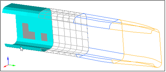
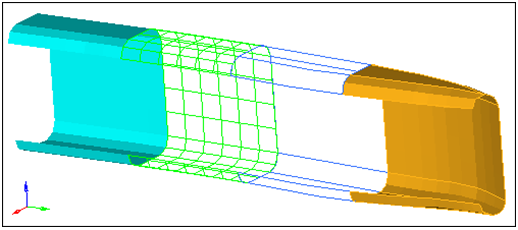
  1. Next to the mid2, end, and rigid components, click (elements).
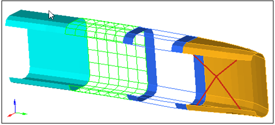
    HyperMesh displays the elements in the center and mid1 components.


    Figure 10.
  2. Place your mouse cursor in the graphics area then on your keyboard, press F.
    HyperMesh fits the displayed components to the graphics area.
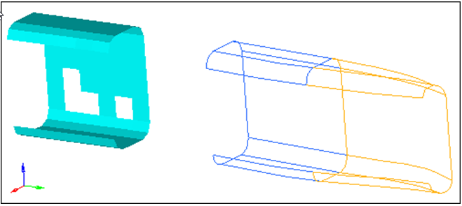
  3. Next to the components mid2 and end, click (geometry).
    HyperMesh displays the geometry in the mid2 and end components.


    Figure 11.
  4. Press F.
    HyperMesh fits the displayed components to the graphics area.

Control the Display of Entities Using Mask Panel

In this step you will control the display of entities using the Mask panel.

  1. To open the Mask panel, click (Mask) on the Display toolbar.
  2. Go to the mask subpanel.
  3. Set the entity selector to elems.
  4. Click elems >> by collector.
  5. Select the component, mid1.
  6. to complete your selection of components, click select.
  7. From the graphics area, manually select a few elements in the center (blue) component.


    Figure 12.
  8. To mask the elements, click the green mask. The elements in the mid1 component and the elements you selected from the graphics area are no longer displayed.
    Note: In the Model Browser, notice that the elements () for the components center and mid1 are still displayed. Their display icons indicate that they are activated even though some or all of the elements in these components are masked (hidden).


    Figure 13.
  9. In the Mask panel, click unmask all, or on the Display toolbar, click (unmask all).
    HyperMesh displays all of the elements in the components, center and mid1, again.
  10. To return to the main menu, click return.

Control the Display of Entities Using Find Panel

In this step you will control the display of entities using the Find panel.

  1. To open the Find panel, click (Find) on the Display toolbar.
  2. Go to the find entities subpanel.
  3. Click elems >> by collector.
  4. Select the component, end.
  5. Click select.
  6. To find the elements, click find.
    HyperMesh displays the elements in the component, end.


    Figure 14.
    In the Model Browser, notice that the elements for the component, end, are now shown as active (). This is because the collector containing the entities that are to be displayed (found) must be active.


    Figure 15.
  7. Go to the find attached subpanel.
  8. Click attached to: elems >> displayed.
  9. To find the elements, click find.
    HyperMesh displays some of the elements in the components, mid2 and rigid. These elements are immediately adjacent and connected to the selected elements.
    Note: The elements for these components are now shown as active. The components were made active so that the elements could be displayed.


    Figure 16.
  10. To return to the main menu, click return.
  11. On the Display toolbar, click (Unmask All).
    HyperMesh displays all of the model's elements.
    Note: This is because the Find panel finds the entities it is supposed to find, activates (displays) the corresponding collectors, and then masks the other entities in the collectors it activated. In this case, the last find command displayed on the components, mid2 and rigid, in the Model Browser.

Change the Display of Entities

In this step you will change the display of entities using the Mask tab.

  1. In the Model Browser, click on any of the white space to make sure nothing is selected.
  2. Click (Display none).
  3. Click (Display all).
    Performing these two steps makes sure that everything is displayed in the model.
  4. Click the Mask tab.
  5. In the Isolate column of Components, click 1.
    HyperMesh displays only the components in the model (elements, geometry, and connectors), and masks everything else.
  6. Expand the Components branch to expose the connectors, elements, and geometry.
  7. In the Hide column of Elements, click .
    HyperMesh masks the elements in the model, and only displays the surfaces.
  8. Expand the LoadCollectors branch to expose loads and equations.
  9. Expand the Loads branch to expose constraints, forces, moments, and so on.
  10. In the Show column of Constraints, click +.
    HyperMesh adds constraints to the display of the surfaces.
  11. Expand the Elements branch to expose 0D/rigids, springs/gaps, 1D, 2D, and 3D.
  12. In the Isolate column of 0D/Rigids, click 1.
    HyperMesh adds rigid elements to the display, and masks the surfaces. The constraints remain displayed.
    Note: When you use Isolate below the top level of the list, HyperMesh will not mask anything outside of the top level that the entity being isolated belongs to. Rigids belong to components at the top level, therefore HyperMesh will not mask any entities in the other top levels.
  13. In the Isolate column of Components, click 1.
    HyperMesh displays all of the entities in the components, and masks the constraints.
    Note: When you use Isolate at the top level of the list (components, groups, loadcollectors, morphing, multibodies, and systemcollectors), HyperMesh will mask everything outside of the entity type being isolated.

Change the Color of Components

In this step you will change the color of components using theModel Browser.

  1. In the Model Browser, Component folder, click the Color icon next to mid1.
  2. From the color pop-up, select a different color.
  3. Observe the change in color of the elements in mid1.