Bounding Box |

|

|

|

|
|
Bounding Box |

|

|

|

|
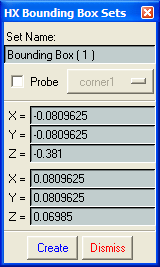
The Bounding Box option on the Editors menu permits the definition of a set of elements through the creation of a bounding box. This box is defined by prescribing coordinate locations for opposite corners and sides parallel to global coordinate axes of a rectangular box. All elements, which have centers within this box, are grouped into a set with a user-prescribed name. The definition of bounding box sets is particularly useful for examination and manipulation of large models. The Bounding Box Sets panel prompts you for the following data:
Field |
Description |
Set Name |
A character string used to identify the bounding box set. This name appears under the Sets option on the Mesh Editor panel and on the Set Selector panel in the Main Viewport. |
Probe |
Activates the probe for selecting corner points of the bounding box. When the probe is active, corner1 or corner2 can be selected for entering the location of the probe in the Bounding Box Sets panel. Occasionally, the probe does not appear on the Main Viewport even when the probe is active. In these instances, select the Solution Probe icon at the top of the Main Viewport to make the cross-hairs reappear on the viewport. |
X,Y,Z Coordinates |
These are the corner points of a bounding box set. These points may be entered directly or by moving the cross-hairs in the probe. |
Create |
Creates the indicated element set. |
Dismiss |
Exits the panel. |
| Note: | Bounding box sets are not saved to the restart file. Once created, bounding box sets cannot be deleted until the current session is terminated. |

The Bounding Box Sets panel