OS-E: 9000 Piezoelectric Analysis of a Cantilevered Bar
This example is used to demonstrate Piezoelectric Analysis using enforced voltage and enforced displacement using Linear Transient Analysis.
Model Files
Model Description
A cantilevered piezoelectric bar meshed with solid elements. In the first load case, the bar is subject to a sinusoidal electric potential at the free end. The applied potential triggers a structural deformation in the material. In the second load case, the output displacement from the previous load case is exported and added as input enforced displacement. This triggers the same voltage response, thereby demonstrating reverse piezoelectric effect.
Boundary Conditions
- In load case 1, the sinusoidal voltage is scaled by an amplitude of 1000 kV and applied at the dependent grid of the MPC.
- In load case 2, enforced displacement (exported from load case 1) is applied on the same MPC grid, to study the output voltage.
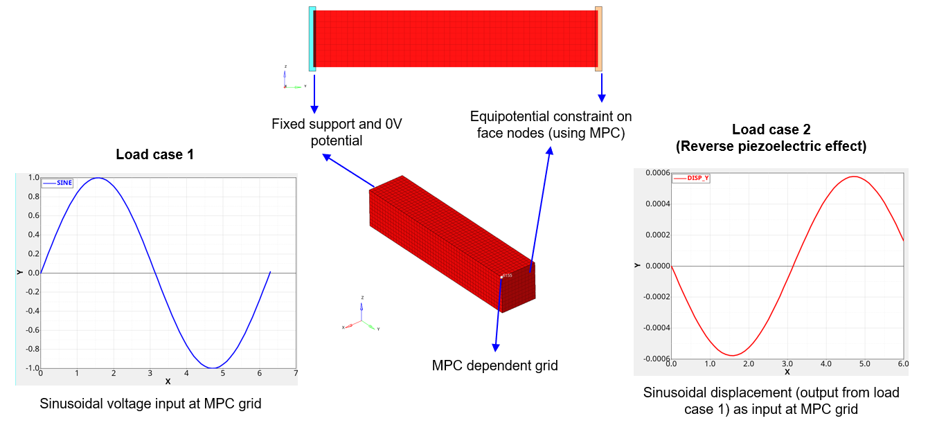
Figure 1. Boundary conditions used in the model
Material Properties
- Anisotropic Dielectric matrix (MAT2PT)
(1) - Piezoelectric coupling matrix (MATPZO) – Strain charge
form
(2) - Orthotropic elasticity coefficients (MAT9OR)
- E1
- 60.61 GPa
- E2
- 48.31 GPa
- E3
- 60.61 GPa
- V12
- 0.512
- V13
- 0.289
- V23
- 0.512
- G12=G23
- 23.0 GPa
- G23
- 23.5 GPa
Results
- Load case 1: Applied sinusoidal voltageIt can be noted that the applied voltage triggers a structural deformation which is also sinusoidal.
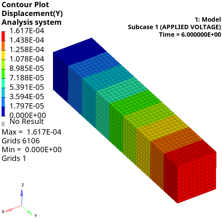
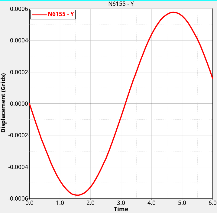
Figure 2. Results for load case 1 - Load case 2: Reverse piezoelectric effect (applied displacement)It can be noted that the output electric potential (plotted at dependent grid of MPC) is identical to the applied voltage in load case 1, thereby demonstrating reverse piezoelectric effect.
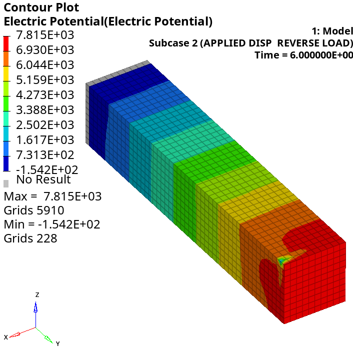
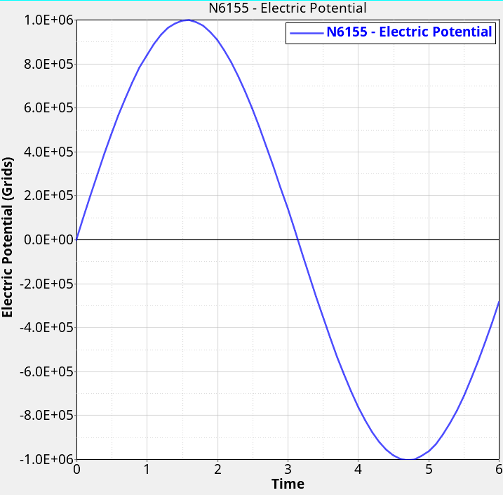
Figure 3. Results for load case 2