Cyclic Hardening
Isotropic
During cyclic loading process, there is elastic unloading and elastic loading in reverse direction until it reaches the maximum yield stress from its history of deformation and then starts to plastically deform as metals has memory of the deformation history.
Kinematic
During cyclic loading process, there is elastic unloading and elastic loading in reverse direction until it reaches the initial yield stress and then starts to plastically deform.
Mixed Hardening
This is a combination of Isotropic hardening and Kinematic hardening using a factor that varies between 0.0 and 1.0. A value of 0.0 indicates Isotropic hardening and value of 1.0 gives Kinematic hardening.
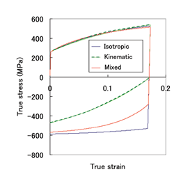
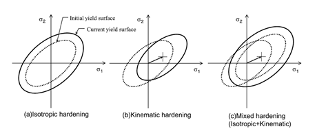 Figure 1. Schematic illustration for Isotropic, Kinematic, Mixed hardening.
Yoshida Hardening
Yoshida hardening is like a mixed hardening law and tends to describe more accurately behavior of a material with two surface models: a) Yield (inner) surface, and b) Bounding surface. Yield (inner) surface follows Kinematic hardening within the bounding surface. Bounding surface follows Mixed hardening law as shown below.
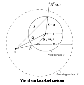
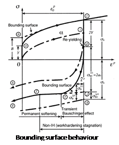
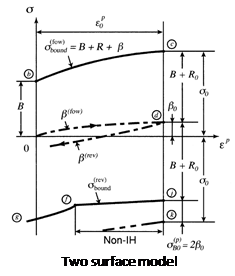 Figure 2. Schematic illustration for Yoshida hardening model
Bounding surface size is described as
![]()
![]()
Bo = Initial size of bounding yield surface
K = Strength coefficient
n = strain hardening
E0 = Pre-strain
b= Saturated value for kinematic hardening of bounding surface
m = Kinematic hardening parameter of the bounding surface
Ep = Plastic strain
![]() =
Yield stress for bounding surface
=
Yield stress for bounding surface
Yield surface is described by
![]()
![]()
![]()
C = Kinematic hardening parameter of the yield surface
Y = Initial Yield stress