Connected Pattern Direction
Check the pattern opposite routed directions.
- Checking
- Check Pattern Direction: Check the pattern direction.

Figure 1.- Target Component Definition: Define target components.
- All SMD Components having 2 Pins: Include all SMD type 2 pin components in the target components list.
- Component Group Selection: Select target components from the component group list.
- Target Object Definition: Define target objects.
- Trace: Target components connecting routing patterns will be target objects.
- Copper: Target components connecting copper-pour will be target objects.
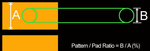
- Exclude Minimum Ratio of Width for Pattern Width to Pad
Width (Pattern Width x 100/ Pad Width): For certain patterns
connected to pad will not be checked. Thinner patterns than
the given ratio will be excluded in checking.

Figure 2.
- Target Component Definition: Define target components.
- Check Similar connected Pattern’s Width for each Pad: Check patterns
which have similar patterns with pad in width.
- Target Component Definition: Define target components.
- All SMD Components having 2 Pins: Include all SMD type 2 pin components in the target components list.
- Component Group Selection: Select target components from the component group list.
- Target Object Definition: Define target objects.
- Trace: Target components connecting routing patterns will be target objects.
- Copper: Target components connecting copper-pour will be target objects.
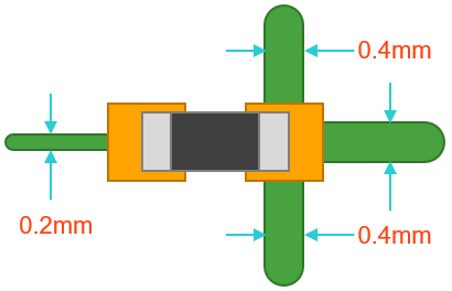
- Allowable Ranges of Comparing Ratio for 2 Connections:
Define allowable range (%) for the connected width compared
to the other side. Difference ratio of copper connection
width: (0.2/(0.4*3))*100 = 16.666%)

Figure 3. - Excluding Net Name Filters: For nets with specifying character string in the name will not be checked.
- Target Component Definition: Define target components.
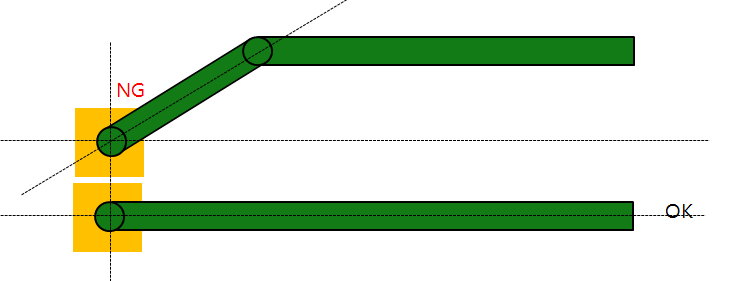
- Check the right angled Pattern from Pad Edge: Check pad connected
patterns are connected with an angle of 90 degree.

Figure 4.- All Components: All components will be target components.
- Component Group Selection: Select target components from the component group list.
- Allow diagonal patterns on the pad corner(only applicable for the rectangle-type pad): Diagonal patterns through the edges of the pad are allowed.
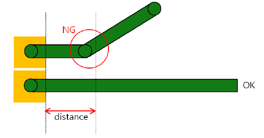
- Keeping a straight the line within a given distance from the
Pad: Check pad connected patterns keep 90 degree within the
given distance.
- When this option is checked, the diagonal pattern passing through the edge of the pad is also subject to checking under the Keeping a straight line within a given distance from the Pad option below.
-

Figure 5.
- Check Pattern Direction: Check the pattern direction.