PollEx Mounting Data Extractor extracts components and PCB information for
chip mounter from PCB design data. It is included in the PollEx PCB Modeler.
Launch PollEx PCB and open layout design file.
Click PollExPCB from the PollEx Launcher.
Click File > Open and open
C:\Temp\Altair-PollEx\Manufacture\MountingDataExtractor\PollEx_New_Sample.pdbb.
Refer to PCB for how to use the
PollEx PCB viewer.
Extract Mounting Parts List.
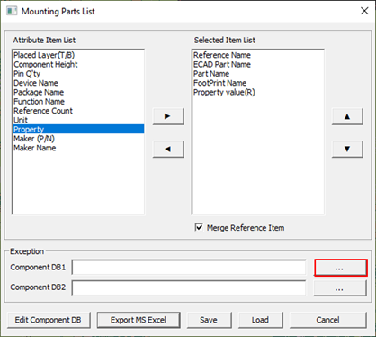
From the menu bar, click Manufacture > Mounting Data Extractor > Mounting Parts List.
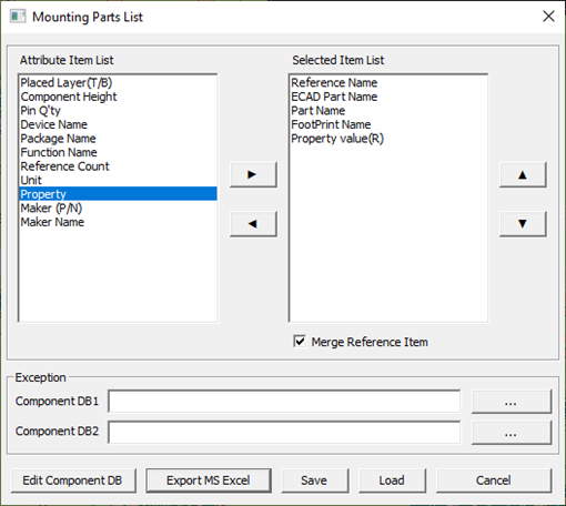
Select attribute items as follows:
Selection is available by double-clicking or by selecting and clicking
the arrow.
Reference Name: already selected by default setting.
ECAD Part Name: already selected by default setting.
Part Name: for display part name of component.
FootPrint Name: for display footprint name of component.
Property Value(R): for display value of component. Select
Value(R) from the menu which you can
see by double-clicking property item.
Figure 1.
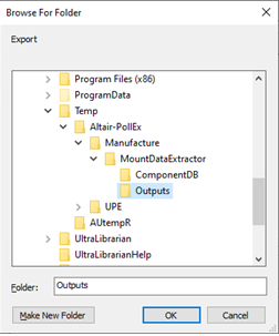
Click Export MS Excel to export output as a
Microsoft Excel file.
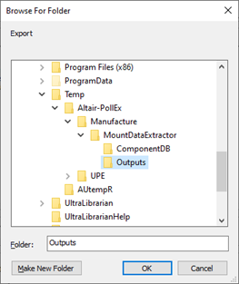
Select the
C:\Temp\Altair-PollEx\Manufacture\MountingDataExtractor\Outputs
folder to save the result Excel file.
If this folder doesn’t exist, create it first. Figure 2.
Click OK to export
the Excel file.
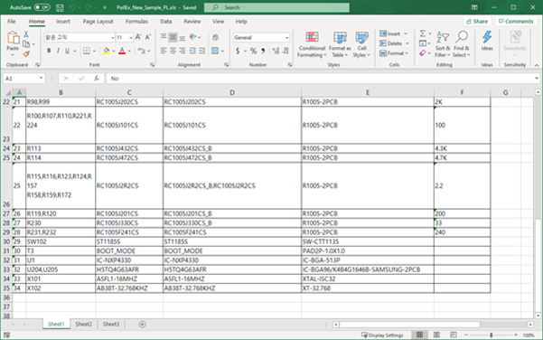
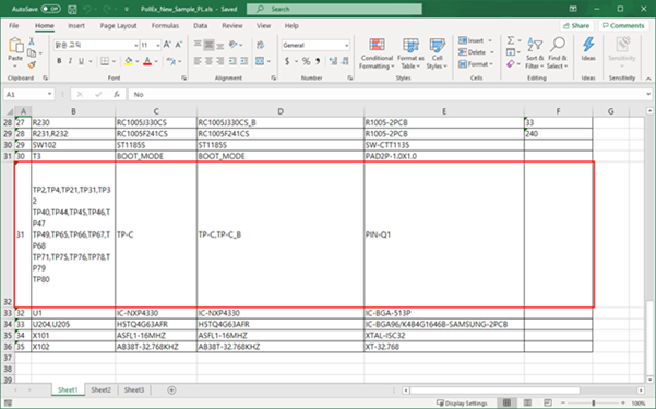
The extracted Excel file is shown in Figure 3. Figure 3.
In the part list Excel file, TP-C is not needed for making
component mounting list, so you need to exclude it.
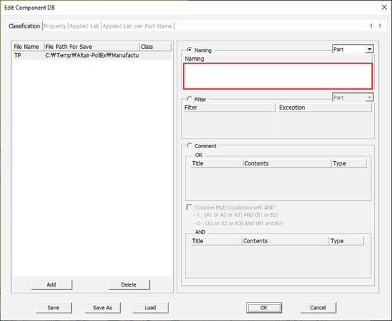
Click Edit Component DB to make a database file
to exclude specific components.
Click Add to create a component database
file.
Select the
C:\Temp\Altair-PollEx\Manufacture\MountingDataExtractor\ComponentDB
folder, enter TP for the database file name, and click
Open.
If the folder doesn’t exist, create it first.
Double-click the Naming list space.
Figure 4.
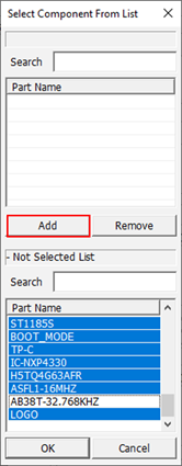
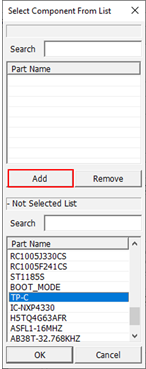
In the Select Component From List dialog, select
TP-C, click Apply, and click
OK.
Figure 5.
Click Save to save current setting.
Select the
C:\Temp\Altair-PollEx\Manufacture\MountingDataExtractor\ComponentDB
folder, enter Exclude for the database file name,
and click Save.
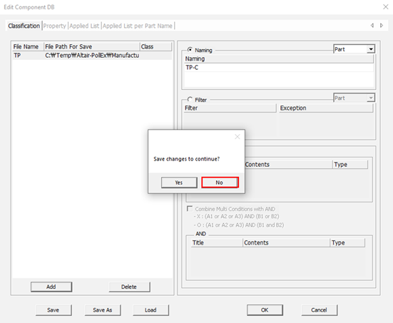
Click OK to finish
setting.
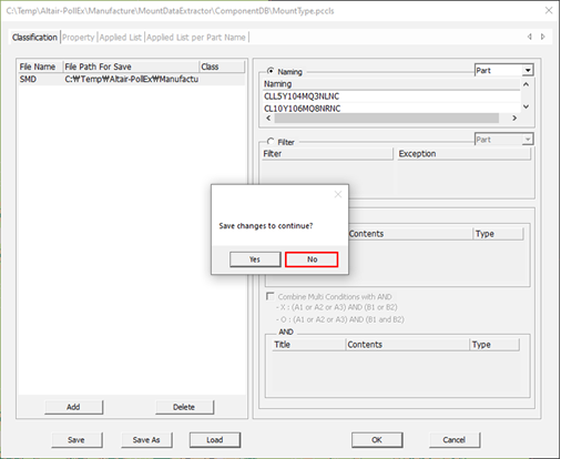
In the Save changes dialog, click
No.
If you want to save the settings as another name, click
Yes and enter another filename. Figure 6.
Click in the right side of Component DB1 list
box.
Figure 7.
Select TP.txt from
C:\Temp\Altair-PollEx\Manufacture\MountingDataExtractor\ComponentDB.
Click Export MS Excel to create a mounting part
list.
Select the
C:\Temp\Altair-PollEx\Manufacture\MountingDataExtractor\Outputs
folder and click OK to
export Excel file.
Figure 8.
In the extracted excel file, the TP-C components are removed. Figure 9.
Click Cancel to finish Mounting Part List.
Extract Mounting Coordinate List.
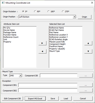
Click Manufacture > Mounting Data Extractor > Mounting Coordinate List.
Select attribute items as follows:
Selection is available by double-clicking or by selecting and clicking
the arrow.
Reference Name: already selected by default setting.
ECAD Part Name: already selected by default setting.
Part Name: for display part name of component.
Reference Location X: to display X coordinate of component.
Reference Location Y: to display Y coordinate of component.
ECAD Rotation Angle: to display rotation angle of
component.
Placed Layer(T/B): to display component placed side.
Component Height: to display component height.
FootPrint Name: to display footprint name of component.
Property Value(R): for display value of component. Select
Value(R) from the menu which you can
see by double-clicking property item.
Mount Type: to display mount type of component.
Figure 10.
Click Edit Component DB to edit SMD type
component database.
Select the
C:\Temp\Altair-PollEx\Manufacture\MountingDataExtractor\ComponentDB
folder, enter SMD for the database file name, and
click Open.
If the folder doesn’t exist, create it first.
Double-click the Naming list space.
Figure 11.
Select all parts except AB38T-32.768KHZ, click
Add, and click OK.
Figure 12.
Click Save and save the current settings as
MountType in the
C:\Temp\Altair-PollEx\Manufacture\MountingDataExtractor\ComponentDB
folder.
Click OK to finish
setting.
In the Save changes dialog, click
No.
If you want to save the settings as another name, click
Yes and enter another filename. Figure 13.
Click in the Mount Type area and select the
database file for SMD type in the
C:\Temp\Altair-PollEx\Manufacture\MountingDataExtractor\ComponentDB
folder.
Click in Exception area and select the TP file in
the
C:\Temp\Altair-PollEx\Manufacture\MountingDataExtractor\ComponentDB
folder as ComponentDB1.
Click Export MS Excel to extract mounting
coordinate list.
Select the
C:\Temp\Altair-PollEx\Manufacture\MountingDataExtractor\Outputs
folder.
If the folder doesn’t exist, create it first.
Click OK to export
Excel file.
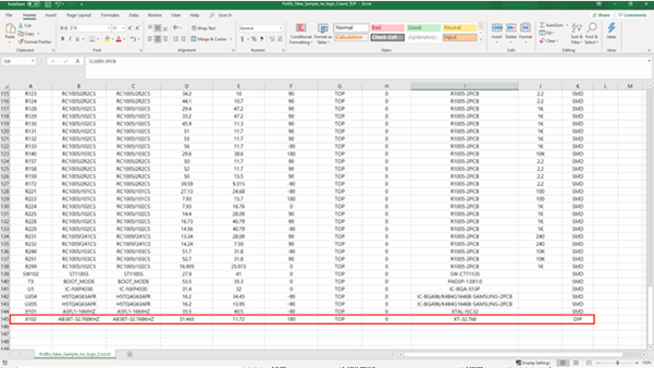
In the extracted Excel file, you can see the mounting coordinate list.
Two files are extracted for the top and bottom side. You can see X102,
which part name is AB38T-32.768KHZ, is specified as DIP. Figure 14.
 in the right side of Component DB1 list
box.
in the right side of Component DB1 list
box.