 icon, in the upper left corner of the
composite state, distinguishes it from a simple state.
icon, in the upper left corner of the
composite state, distinguishes it from a simple state. A composite state is a state with at least one region. The
icon, in the upper left corner of the
composite state, distinguishes it from a simple state.
When you open the dialog box for the composite state block, you can adjust its size by dragging the diagonal lines in the lower left corner.
Icon

Regions are created in the Decomposition Compartment. If a composite state contains at least two regions, it is referred to as an orthogonal composite state. Each region, in an orthogonal composite state, has a set of states and transitions that can execute in parallel, but cannot transition between regions. Each region can support an active state and take transitions in parallel with other regions of an orthogonal composite state.
Any state within a region of a composite state is called a substate of that composite state. If the substate is not contained by any other state, it is called a direct substate; otherwise, it is referred to as an indirect substate.
Each region of a composite state may have an initial state indicator and a final state. A transition to the enclosing state represents a transition to the initial state indicator in each region. A transition to a final state represents the completion of the enclosing region. Completion in all orthogonal regions represents completion of the enclosing state. Completion of the topmost regions of a composite state corresponds to its termination.
If a transition terminates on an enclosing state and the enclosed regions do not have an initial pseudo-state, it is considered an ill-formed model. That is, the initial pseudo-state is mandatory.
For information on editing composite states, see Working with states and pseudo-states.
Constraints
•A region can have at most one initial state indicator
•A region can have at most one deep history pseudo-state
•A region can have at most one shallow history pseudo-state
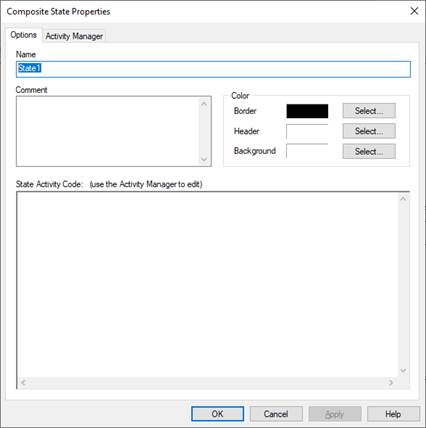
Background: Specifies the color of the decomposition region of the state.
Border: Specifies the color for the state borders.
Header: Specifies the color of the header region. To change the font color, use the View > Fonts command.
Comment: Indicates information or notes about the state. The comments only appear in the dialog box.
Name: Specifies a name for the state. The name can be alphanumeric characters. It must be unique with respect to other state names in the state chart.
State Activity Code: Specifies one or more actions and associated behaviors. Enter and edit state activity code in the Activity Manager window.
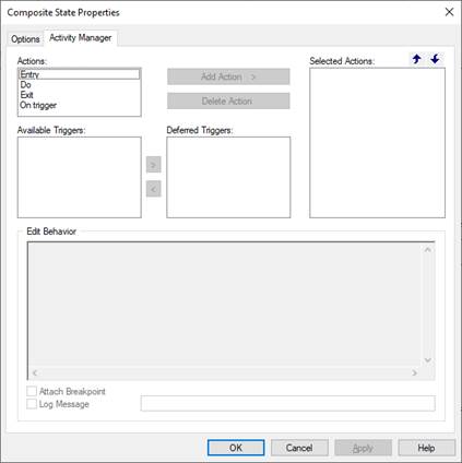
Entry: Code is executed on state entry.
Exit: Code is executed on state exit.
Do: Code is executed for each execution cycle that the state remains active.
On Trigger: Code is executed when the state is active and when the specified trigger is TRUE.
Add/Delete Action: Adds or deletes the action to the Selected Actions window.
Attach Breakpoint: Sets a breakpoint the state that causes the simulation to stop after the corresponding Embed time step is complete. For more information, see Using breakpoints.
Available Triggers: Lists the available triggers.
Deferred Triggers: Lists the deferred triggers.
Edit Behavior: Specifies the state behavior for the corresponding action. State behavior is specified as C statements. For more information, see Associating behaviors with states
Log Message: Logs the specified message when a state behavior is executed. For more information, see Logging messages.