Category: Toolbox > eDrives and Systems > eMotors > Controllers > Stepper Control
Inputs:
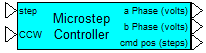
•step: Specifies logic transition input (0 to 1). The rising edge of this input causes the motor to move by one microstep (one microstep is equivalent to the specified step resolution).
•CCW: Specifies logic level input (0 or 1). When CCW is true (1), the motor steps in a counter-clockwise (CCW) direction. When CCW is false (0), the motor steps in a clockwise (CW) direction.
Outputs:
•a Phase: Connects to “a” phase input of the Permanent Magnet Stepper Motor-2 Phase block. Units are in volts.
•b Phase: Connects to “b” phase input of the Permanent Magnet Stepper Motor-2 Phase block. Units are in volts.
•cmd pos: Provides the current commanded step position in steps (actually microsteps).
Description: The Microstep Controller block simulates the operation of microstep control. Microstep control is typically implemented in a microprocessor, commercial IC, or ASIC for precision incremental motion of 2-phase permanent magnet stepper motors. The controller can be used for open-loop positioning or speed (slew) control applications, or used as a component in a step motor closed-loop control system. Logic inputs provide step activation and directional control. A counter output is provided to track the current commanded (accumulated) position in steps.
Note that the slew rate (speed) of the motor in steps/sec depends on the input pulse rate. Actual shaft (angular rate) depends on this pulse rate. The main feature that differentiates the Microstep Controller block from the full/half step controller is that the Microstep Controller can provide much smaller fractions of a full step. (One full step of a step motor in degrees is 360/(number of rotor teeth)). The Microstep Controller provides phase output voltages that are proportional to the sine and cosine of the commanded step angle, and based on the known number of rotor teeth. For an actual microstep controller, the ultimate positioning resolution depends on the LSB voltage resolution of the digital to analog converters or the power amplifier/system’s noise floor. This model assumes no limitations are introduced by these components.
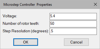
Number of Rotor Teeth: Indicates the physical number of teeth in rotor.
Step Resolution: Defines the control resolution. Units are in degrees.
Supply Voltage: Defines the RMS voltage level of the phase voltages through one cycle of motor rotation. Units are in volts.
Diagram name: Micro Step Controller
Location: Examples > eDrives and Systems > eMotors > Steppers
This example illustrates a typical application where a stepper motor is used in feedback with an optical encoder.
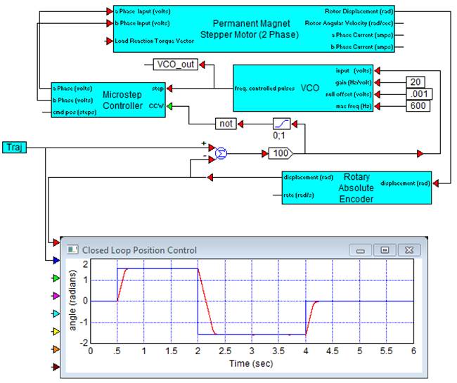
A Rotary Encoder block is used to directly measure shaft position of the stepper motor. Angular displacement is compared against the trajectory. The error is amplified with a high gain to saturate the VCO (Voltage Controlled Oscillator) input and drive the motor to the maximum specified slew rate (600 steps/sec). Since only proportional control is used, the VCO quickly desaturates as the motor closely approaches the target trajectory. The sign of the comparator provides direction control as a 0 or 1 in the Microstep Controller.
In this example, microstep resolution is set at 0.1o. Closer examination of the rotor position shows a limit cycle once the motor reaches its trajectory. This hunting could be eliminated using deadband or other logic mechanisms that could easily be implemented using other standard Embed blocks.
The disadvantage of this type of controller is the expense and complexity of using an encoder for feedback and having to use additional control logic. The advantage is that if the motor inadvertently loses step, it will recover and eventually reach the targeted command. Stepper motors may sometimes lose step if external disturbance torques are encountered that exceed design torque, or if the motor is slewed too quickly.