Category: Toolbox > eDrives and Systems > eMotors > Motors
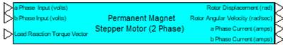
Description: The Permanent Magnet Stepper Motor-2 Phase block uses the set of coupled nonlinear differential equations that describe motion of a 2-phase permanent magnet stepper motor with bipolar windings (4 wire input). Typical linear electrical and mechanical properties are provided, as well as nonlinear properties, including bearing stiction and Coulomb friction for a high-fidelity simulation of stepper motor dynamics. The number of rotor teeth determines the full step angle (resolution) of the motor. The step angle in degrees is equal to 360/(number of rotor teeth).
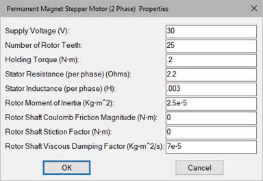
Holding Torque: Represents the motor holding torque. Units are in N-m/amp.
Number of Rotor Teeth: Indicates the physical number of teeth in the rotor.
Rotor Moment of Inertia: Represents the rotor moment of inertia with respect to the axis of rotation. Units are in Kg-m2.
Rotor Shaft Coulomb Friction Magnitude: Allows specification of constant directional dissipative force (Coulomb model) in units of N-m.

Rotor Shaft Stiction Factor: Allows specification of a stiction force value or break-away torque. This parameter is normally not specified by the motor manufacturer, but can be obtained experimentally. Units are N-m.

Rotor Shaft Viscous Damping Factor: Indicates the factor that linearly relates viscous damping force to angular velocity. This parameter is normally not specified by the motor manufacturer but can be determined experimentally. Units are kg-m2/s.
Stator Inductance (per phase): Represents the inductance of the stator coil windings (per phase). Units are in henries.
Stator Resistance (per phase): Represents the resistance of the stator coil windings (per phase). Units are in ohms.
See the examples included with the Stepper Motor Controller and Microstep Controller blocks for application of the Permanent Magnet Stepper Motor (2 Phase) block.