Category: Toolbox > eDrives and Systems > eMotors > Controllers > Stepper Control
Inputs:
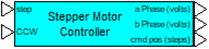
•step: Specifies logic transition input (0 to 1). The rising edge of this input shifts the control sequence one increment, causing the motor to move by one step (one half step if the half step checkbox is selected.
•CCW: Specifies logic level input (0 or 1). When CCW is true (1), the control sequence moves the motor in a counter-clockwise (CCW) direction. When CCW is false (0), the control sequence moves the motor in a clockwise (CW) direction.
Outputs:
•a Phase: Connects to “a” phase input of the Permanent Magnet Stepper Motor-2 Phase block. Units are in volts.
•b Phase: Connects to “b” phase input of the Permanent Magnet Stepper Motor-2 Phase block. Units are in volts.
•cmd pos: This output provides the current commanded step position. Units are in steps.
Description: The Stepper Motor Controller block simulates a typical full/half step bi-directional controller for operating incremental motion of 2-phase permanent magnet stepper motors. The controller can be used for open-loop positioning or speed (slew) control applications or used as a component in a step motor closed-loop control system. Logic inputs provide step activation and directional control. A counter output is provided to track the current commanded (accumulated) position in steps.
Note that the slew rate (speed) of the motor in steps/sec depends on the rate of input pulses. Actual shaft (angular rate) depends on this pulse rate and the characteristics of the stepper motor (number of rotor teeth). Full step resolution of the motor is 360/(number of rotor teeth) in degrees. Selecting half step operation can increase incremental resolution.
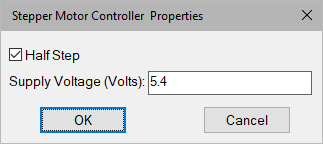
Half Step: When this checkbox is checked, the controller issues pulse sequences that step the motor in half step increments. When this checkbox is not checked, the controller issues full step increments.
Supply Voltage: Defines the voltage level of phase a and b pulses. Units are in volts.
Diagram name: Stepper Motor Controller
Location: Examples > eDrives and Systems > eMotors > Steppers
This example illustrates a typical application where a processor commands a step motor to increment to a specified step count at a specified slew rate.
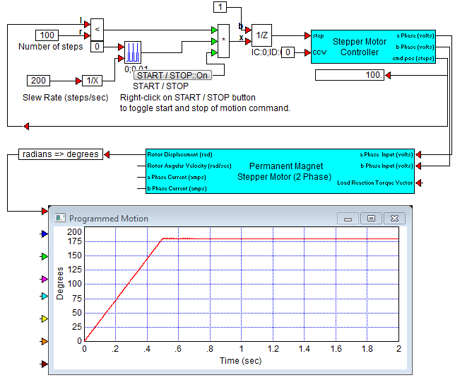
Here the counter (cmd pos) output is used to compare against the set value of 100 steps. When the counter reaches the 100th step, the conditional < block output becomes zero. This closes the gate (multiplier block) for any further pulses issued by the pulseTrain block. The Time Between Pulses parameter for the pulseTrain block determines slew rate, and the operation is executed manually by clicking the Start button. The unitDelay block, used after the multiplier, allows perfect matching of counter to targeted step position, as well as preventing an algebraic loop. In this example, the stepper motor was specified having 50 rotor teeth making the full step 1.8o, and the controller was set for half stepping (0.9 o) Thus total angular displacement is 90o.
The advantage of open-loop control, as shown by this example, is that it is inexpensive; that is, it does not require sensors for feedback. The disadvantage is that positioning errors can occur if external shaft torque exceeds designed limits, causing the motor to lose steps. Open-loop systems may sometimes require periodic homing maneuvers that check actual shaft position against hard stops, limit switches, or sensors. Such systems and devices can also be simulated using Embed blocks.