Creating the Model
Create the model in CADFEKO. Define any ports and sources required for the model. Specify the operating frequency or frequency range for the model.
-
Create a dielectric medium.
- Label: RogersDuroid5870
- Relative permittivity: 2.2
- Dielectric loss tangent: 0.0012
-
Add a planar multilayer substrate (infinite plane) with a conducting layer at
the bottom.
-
Select Plane / ground.
- Click Planar multilayer substrate.
- Thickness (Layer 1): 2.5e-3
- Medium (Layer 1): RogersDuroid5870
- Ground plane (Layer 1): PEC
- Z value at the top of layer 1: 0.
-
Select Plane / ground.
-
Create the branch coupler.
-
Import the Parasolid model from file
Tip: On the Home tab, select Import and select Geometry. Browse for the feedNetwork.x_b Parasolid file.
-
Import the Parasolid model from file
- Create four microstrip ports on the four terminals of the network. Number the ports anti-clockwise.
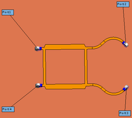
Figure 1. 3D view of the feed network showing the port
numbering in CADFEKO.
- Add a 120 Ω load on Port4.
-
Set the frequency.
- Continuous interpolated range
- Start frequency (Hz): 0.8*2.4e9
- End frequency (Hz): 1.2*2.4e9
- On the Export tab enable Specify
number of samples for exported data and enter a value of
100.Note: The setting for export will ensure that the exported Touchstone file will contain 100 frequency samples.