Validating the Model in POSTFEKO
View the model using visualisation tools in POSTFEKO to ensure the model was created as intended.
Ensure the horn model is open in the 3D view.
By default the mesh edges of the model is not displayed in the 3D view.
-
Enable the mesh edges.
-
On the 3D View
contextual tabs set, on the Mesh tab, in the
Visibility group, click the
 Metal icon. From the drop-down list, select the
Edges check box.
Metal icon. From the drop-down list, select the
Edges check box.
-
On the 3D View
contextual tabs set, on the Mesh tab, in the
Visibility group, click the
Disable the display of the symmetry planes.
-
On the 3D View
contextual tabs set, on the Display tab, in the
Method display group, click the
 Symmetry icon.
Sources in the model are displayed by default.
-
Disable the display of sources in the model.
-
On the 3D View
contextual tabs set, on the Display tab, in the
Entities group, click the
 Sources icon.
-
On the 3D View
contextual tabs set, on the Display tab, in the
Entities group, click the
To view the full-length horn in the 3D view, zoom the horn to the extents of the window.
-
Zoom to extents of the 3D view using one of the following
workflows:
- On the View tab, in the
Zooming group, click the
 Zoom to extents icon.
 - Press F5 to use the keyboard shortcut.
- On the View tab, in the
Zooming group, click the
Enable the tick marks on the axes.
-
On the 3D View
contextual tabs set, on the Display tab, in the
Axes group, click the
 Tick marks icon.
-
Use the distance measurement tool to validate the dimensions of the horn.
-
On the 3D View
contextual tabs set, on the Mesh tab, in the
Tools group, click the
 Measure distance icon.
The distance is displayed at the bottom of the Measure distance dialog.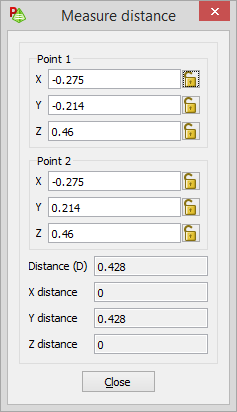
-
On the 3D View
contextual tabs set, on the Mesh tab, in the
Tools group, click the