Flux e-Machine Toolbox: Input parameters
Introduction
After having opened the coupling component in Flux, the user must define several input parameters before running a test. These parameters allow to:
- pilot the solving of the Flux project
- specify solving options (distribution, memory)
- compute and build the different performance maps
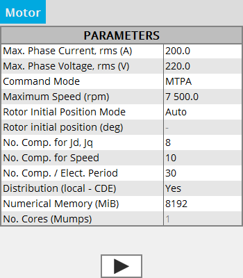
Input parameters : Wished data
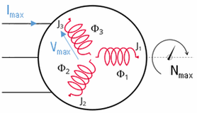
- Maximum phase current RMS
- Maximum phase voltage RMS
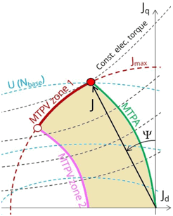
- Command mode:
- either MTPV: the Maximum Torque Per Volt
- either MPTA : the Maximum Torque Per Amper
- Maximum allowed rotating speed for the electrical machine
Input parameters: Rotor initial angle
The Rotor initial angle is a necessary variable in order to apply Park’s transforms. Two possibilities:
- User: the user knows the initial angle of the rotor and can enter the value
- Auto: the value of the initial angle of the rotor is computed automatically. The goal is to find the rotor angle for t=0s in order to align it with the magnetic flux density in the airgap generated by the reference phase (e.g., phase A). Two simulations are performed in order to compute rotor initial angle. A path in the middle of the airgap is automatically defined in order to compute the magnetic flux density within it.
Input parameters: Number of computations requested
- Number of computation for Jd and Jq (8 by default)
- Number of computations for the speed (10 by default)
- Number of computations by electrical period (30 by default)
As a reference, for 20000 computation points on a server with 22 cores with 8 Mio (GB) of numerical memory, a 2D project is solved in 5h. With this same project, with 75000 computation points (Id and Iq at 10, Speed at 15 and Nb of computations by electrical period at 50), results will be more accurate but with a solving time around 24h.
Input parameters: Options of distribution and memory
- Activate or not the local distribution CDE (Computing Distribution Engine).
The number of cores must be defined in the configuration of CDEAttention: Make sure the service is installed and enabled. If this is not the case even with the option to Yes, the solving will be sequential and not distributed.Note: The computing distribution is not implemented in Skew.
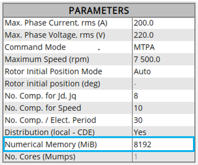
- Numerical memory allocated to the solving process of the Flux
project:
Since FeMT 2021, there is a new memory mode to run tests: the Dynamic memory mode.
From now on, there are two memory modes: User (static) and Dynamic.
- If the User (static) memory mode is used,
then the numerical memory value (in MiB) allocated to the solving
process of the Flux project is displayed. The user can modify this value.
Note: The user can not switch to the Dynamic memory mode in FeMT. In order to run tests in Dynamic memory mode, the user will have to regenerate the coupling component from a Flux running in Dynamic memory mode. - If the Dynamic memory mode is used, then
Dynamic is displayed and the numerical
memory used is dynamically managed by Flux during its execution. So
in this mode, the user does not set any value for the numerical memory.
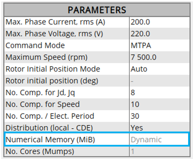
Note: The user can not switch to the User memory mode in FeMT. In order to run tests in User memory mode, the user will have to regenerate the coupling component from a Flux running in User memory mode.
- If the User (static) memory mode is used,
then the numerical memory value (in MiB) allocated to the solving
process of the Flux project is displayed. The user can modify this value.
- Number of cores used by the Mumps solver for the initial project
- If the local distribution via CDE is Yes, the value of the number of cores used by the Mumps solver is fixed at 1, and non accessible for the user, (in this case the parameter is grayed out, which means that the indicated value is not taken into account)
- If the local distribution via CDE is No, the user value of the number of cores is taken into account by the Mumps solver. By default this value is 4.
- In the case where the local distribution via CDE is Yes, but CDE is not correctly configured, the number of cores entered will be taken into account by the Mumps solver.